- Home
- Blending Basics
- Blending vs Dosing
- Dosing Basics
- Liquid Dosing
- Maintenance
- Process Integration
- High Volume Blending
- General Questions

Process Integration and Layout-Dosers
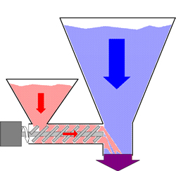
Dosing units for color and/or additives are installed on the processing machine throat and are designed to provide doses of an additive to the flow of material as it gravity flows to the machine throat. These devices provide the ability to dose at a specific rate through the use of a variable speed motor or gear reduction. In addition, for injection molding, they are designed to dose for a programmable amount of time, synchronized with the processing screw retraction.
Installation of a dosing unit requires installing an adaptor onto the throat of the processing machine. Whatever devices are used to provide for the flow of the main material (IE: virgin material) are mounted to the top of this adaptor. The installation objective is to allow the main flow of material to pass unhindered to the machine throat, but with the addition of the color or additive, provided by the dosing unit, which is connected to the side of the throat adaptor. The throat adaptor may be installed in a number of orientations and care should be given that the dosing unit itself, attached to the throat adaptor is oriented in the desired direction for easy access, avoidance of heat, mechanical safety, etc. Check orientation before the adaptor is installed onto the machine throat.
The dosing unit includes several key components, including the metering device (usually an auger), the drive system (usually a motor), and a supply hopper for the additive, plus a control. The control may be part of the dosing unit or located elsewhere. Considerations for all these components should be made, specifically the supply hopper. The supply hopper will receive the most day-to-day attention, so it should be accessible for filling, cleaning, etc. Plan ahead for the use of an automatic loading device on top of the hopper, otherwise the unit will have to be hand-filled. Most important, is the clearance between the dosing hopper and the main material supply hopper. Rudimentary measurements should be taken beforehand, especially if the dosing unit and the supply hopper manufacturers are different. Determine if all equipment will fit prior to beginning installation. Conflicts, i.e. the additive hopper will not fit with the main supply hopper in place, may require the use of an additional riser to assure clearances will be adequate for hand filling or loading equipment. Other equipment selections may be required for a suitable installation if there are dimensional conflicts,.
Dose sampling is usually required to calibrate the dosing unit with the additive to be metered and most dosing units are equipped with provisions for sampling. The provision for calibration with your specific unit should be reviewed to assure that your installation allows for easy exercise of this function. It is important to the accuracy of the dosing operation. Some gravimetric units require this function less frequently.
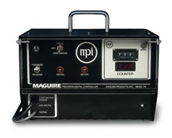
The dosing control provides the speed setting of the dosing motor and when used in injection molding, also provides the setting for the duration of the metering cycle. The control should be installed in a convenient location if it is not already part of the dosing unit. Most dosing units run on single phase power, common to the country or region where sold.
Dosing units used in extrusion (continuous operation) processes run continuously and typically have the option of being connected into the DC drive system of the extruder so that the dosing speed is slaved to the speed of the extruder. This additional connection varies by doser manufacturer and should be researched carefully before attempting connection to the extruder control. Care should be taken to assure it is done correctly and according to code, but also acknowledgement that the dosing control will now have two sources of power: One to operate the unit and one to regulate the speed from the, otherwise independently operating, extruder. Simply disconnecting the power cord of the doser control will only disconnect one power source.
Dosing units used in injection molding (intermittent operation) are usually set up to run at intervals triggered by the press. They will have a second cable that connects them to the injection molding control that will tell the dosing unit when to operate. Timers within the dosing control will determine how long after receiving the press signal that dosing should occur and for how long, or the molding machine may provide full logic for the dosing sequence and no timers are used in the dosing control. In addition, the speed of the dosing maybe set to assure that additive dosing occurs for the duration of the screw retract cycle, for optimum metering.
Some dosing controls include a meter or other speedometer method to indicate the speed of the metering motor for the benefit of easy calibration and making changes.
Some dosing units allow for the use of two (or three or four) dosing units on a single throat adaptor for equipment redundancy and/or multiple additive dosing. Usually, these units operate independently even though they are all installed on a common throat.