
Tooling: What You Need to Know About Jump Gates
Many molders don’t care for jump gates because they have to process around them. But here are some tricks of the trade.

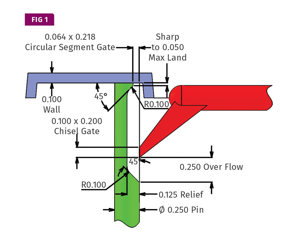
A typical split-pin jump-gate design.
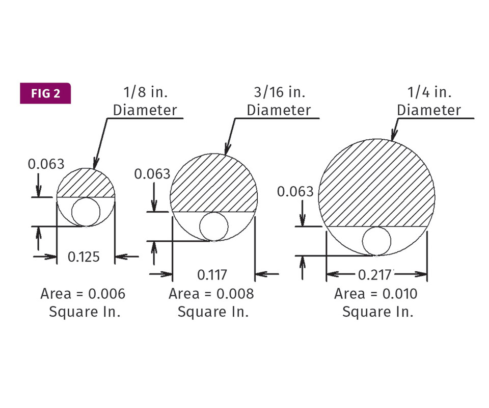
Three different-diameter ejector pins with equivalent (0.006 in.2) flow areas, but much different depths.
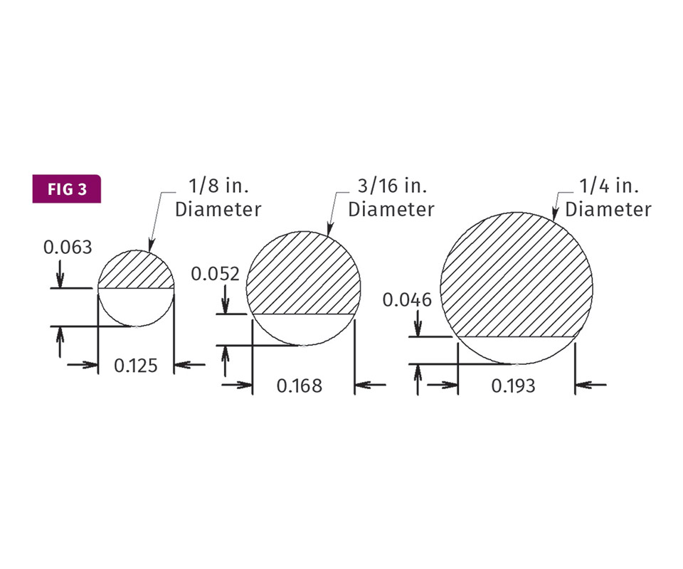
Three different-diameter ejector pins with equivalent relieved depths (0.063 in.), but much different flow areas.


The aptly named jump gate is used to gate indirectly into a feature beyond the outer edge of a part. This gating method is used when the aesthetic requirements prohibit any type of gate scar on an exposed outer surface, because the material enters the cavity from the interior or underside of the part. Jump gates increase the flexibility of where you can locate a gate, which can be very advantageous when the thickest wall section is otherwise inaccessible.
However, many processors don’t care for jump gates. They often must process around various issues they can cause. This column is intended to help you understand and avoid those issues.


From time to time, a mold designer will tunnel gate into a tubular boss for a screw, or into a thin interior rib. Technically, these are not jump gates; they are ordinary tunnel gates because they gate directly into the part. To be considered a jump gate, the mold designer specifically adds a feature, such as a cylindrical boss formed by a shortened ejector pin, into which to gate. Unless this boss has a relatively small diameter, you will probably have a hard time eliminating an opposing sink mark on the exterior surface of the part. This is why the most common jump-gate design is where a tunnel gate feeds into the side of a machined ejector pin.
The pin is relieved on one side, sometimes as much as half its diameter. This ejector pin is often referred to as a “split pin.” The material flows through the tunnel gate and into the void created by the machined pin. From there, it flows up the void and into the cavity. Figure 1 is an example of a typical jumpgate design of this sort.
When a part with a split pin is ejected, a D-shaped stem of material remains attached to the part. Sometimes it is acceptable to leave this stem attached. Sometimes it can simply be bent over while it’s still warm, so as not to interfere with an adjoining part. The more common scenario is that it needs to be completely removed. It is important to know exactly what is required to deal with this stem after the part is molded, because it will affect how you should design the split pin.
Split pins should be made of through-hardened steel.
The split pin must be keyed for proper orientation and the flat side cannot face the top of the mold, unless you use a robot to extract the part. Otherwise, the part could hang up on the pin and get crushed when the mold closes. If you’re not going to use a robot, the flat side of the pin should preferably face the bottom of the mold, so that the part will fall down unobstructed. It will usually fall freely if the pin faces the operator or non-operator sides of the mold, or any angle in between.
Split pins should be made of a through-hardened steel, such as M2, with a 58 to 62 Rockwell hardness. Standard ejector pins are nitrided and have a thin, brittle casing that can chip or crack. There is no need to vent a split pin, because any outgasses are going to flow into the nonrestricted material flow path. If the split pin is installed in a soft or non-heat-treated core, it is a good idea to install a fixed sleeve for the pin to ride in. The sleeve should be made of a different type of steel and preferably have a 10-point Rockwell hardness differential to prevent premature wear or galling. A sleeve made of H-13 with both the ID and OD nitrided to 65 to 74 Rockwell C works very well for this application.
The reason for the hardened sleeve is that there is a lot of plastic pressure pushing the split pin off to one side. The pin will rub against the side of the core and over time, create an egg-shaped hole, which will soon develop down-flash. If you are going to use a sleeve, it must be keyed, and the portion of the tunnel gate machined in its side should be stepped down about 0.005 in. per side, so as not to create a hang-up.
Know How Tooling: Get More Insights on Tooling From Our Expert Authors
Most people consider the tunnel-gated stem to be an added feature of the molded part. That may be true, but that train of thought can get you into trouble. It helps if you don’t consider the tunnel gate to be the gate. Instead, think of it as a restrictive section of the coldrunner delivery system. The void on the side of the ejector pin should be considered a half-round runner, and the tip of the pin to be the actual gate feeding the part. This will give you an entirely different perspective on what size and shape to make the split pin and the tunnel gate. That’s important because the most common problems I have seen with jump gates are blush and sink marks on the surface of the part directly opposite the tip of the split pin. So, let’s start at the tip of the split pin and work our way toward the primary runner.
Assume you were going to edge-gate a part. Depending on the type of molding material, you might use a gate depth that is 50-80% of the part’s wall thickness, and depending on the flow length, the width of the gate being two to six times its depth. Multiply the desired depth by the desired width and you get the flow area in square inches. At a minimum, you want that same flow area where the tip of the split pin meets the part.
One of the biggest mistakes you can make is failing to consider the appropriate diameter of the split pin and the appropriate size of the gate. All too often, the same pin diameter used to eject the part is used to make the split pin because it “looks” right, and the depth of the gate is based on a diameter often used to determine the size of an elliptical gate. There’s a lot more to it than that.
Figure 2 shows three common ejector-pin sizes that have been machined to form the “D” shaped void—all of them 1/16 in. deep. Even though the depths of the gates are the same, they have considerably different flow areas, flow-length capabilities, and gate-freeze times.
Figure 3 shows the same three ejector-pin sizes machined to form the D-shaped void—this time all of them have the same exact flow areas. These three pins also have considerably different shapes.
But in this case, the smaller, 1/8-in. diam. pin will work better for eliminating sink marks on thicker parts because it is deeper and will remain open longer. The larger, .-in. diam. pin will work better for maximizing the flow length on long, thin parts because it is wider and will freeze off sooner. You need to ask yourself, “What does my part need?” and select the split-pin diameter, flow area and gate depth accordingly. Keep in mind, if gate blush is an issue, a deeper gate will usually help. It allows a slower fill speed with less shear to be used without the gate freezing off before the part is packed out.
If this were a standard edge gate, the next thing you would do is specify the land length—typically half the depth of the gate, but never more than 0.050 in. But this is where you need to know what is going to be done with the D-shaped stem after the part is molded.
If you are going to leave it on, then use a typical land length. If you are going to bend it over, you might add a small radius just past a typical land length. If you are going to cut it off, use a typical land length, but make sure there is ample room for the operator to easily get a gate cutter into position down at the base of the stem.
Never let the tunnel gate freeze off before the tip of the split pin.
However, if the material is brittle, you don’t want any land length at all. If the tip of the pin has a large reverse taper with a dead-sharp edge, it creates a notch-sensitive line and the operator may be able to simply flex the segment once to snap it off. Sometimes you get good results when the part is still warm. Sometimes the results are better when it’s cold. There is a small risk with this type of degating method. Depending on the gate size and the wall thickness of the part, you can get a white stress mark on the surface of the part caused by the stem bending a little before it snaps off.
You can have almost any transitional shape between the end of the gate land and the beginning of the relieved section of the pin, such as a 45° angle or a full radius. I prefer a combination of the two—as if it were the end of a parabolic runner. Just don’t use anything that could generate unwanted shear or create problems with the part falling freely off the pin, such as machining a right angle.
Now that the land area and the transition are taken care of, the next thing to do is determine the amount of steel to remove from the pin to form the runner section. If this were a two-plate, fullround cold runner, you would probably make the diameter of the runner feeding the gate approximately 1-1.5 times the thickest wall section of the part for free-flowing materials, or 1.5-2 times the thickest wall section for more viscous materials.
Obviously, this is a general rule of thumb. If you want to calculate the pressure drop empirically, or if you have a flow analysis performed, these would give you a more accurate value of the best size to use. Now calculate the cross-sectional area of that round runner and machine the split pin to have at least an equivalent amount. It would be best to go a little deeper because the pressure drop in a full-round runner is a lot less than a half-round, or circular-segment-shaped runner.
The relieved portion of the pin should extend beyond where the tunnel gate feeds into it. If this were a two-plate cold runner, you would add an overflow approximately 1.5 times the diameter of the runner to catch and retain any solidified material at each runner turn. Why should this be any different?
During ejection the split pin advances and the tunnel gate withdraws from its bore. Since the split pin has zero taper, the tunnelgate orifice must be extremely sharp. Any ragged edges can cause small plastic shavings to lodge inside the hollow tunnel-gate bore. If the overflow in the split pin is insufficient, on the next shot you will see small specks on the outer surface of the part.
The last item to consider is what type of tunnel gate to use and what size to make it. While elliptical tunnel gates are one of the least expensive to machine, my preference has always been the chisel-type tunnel gate. It forms a rectangular gate that is less prone to flaking and is excellent for tweaking a mold after the initial sampling. Since we are gating into a runner and not into a gate, the size of the tunnel gate should be considerably larger than you might normally choose. You never want the tunnel gate to freeze off before the gate at the tip of the split pin. That is the primary reason why you get sink marks on the surface of the part opposite the pin. I suggest the flow area and the depth of the tunnel gate be no less than 1.5 times the flow area and depth of the gate at the tip of the split pin.
Figure 4 is an example of an improved jump-gate design. This mold designer did not like the negative aspects of material flowing through a circular segment. So, he machined a tab into a custom-made blade ejector, which mimics a conventional trapezoidal cold runner. He left a sufficient area to form a cold well, and fed the tab using an appropriately sized chisel-type tunnel gate.
The most common problems with jump gates are blush and sink marks on the surface of the part.
While writing this article, I was reminded of something I’d like to share. Despite decades of experience and a wealth of information available on the internet and in trade books, I always ask my peers to review my articles before submitting them for publication. Growing up, one of my father’s favorite words of advice was, “No one has a monopoly on brains.” My dad, Lazzaro Adam Fattori, passed away Jan. 14, 2016. He was a World War II vet and was very well-known and respected in the injection molding and moldmaking industries.
I was once at a very large and well-respected tool shop in Europe, inspecting some molds we had ordered. The owner of the tool shop pulled my father aside and asked for his advice on a particular mold design problem he was having. A customer of his had rejected a very large and expensive mold for an automobile dashboard. It had an edge gate on the bottom of the dashboard, which left an objectionable knit line where the material flowed around the cutout for a gauge.
My father took a quick look at the mold drawings but didn’t see a solution. I took a look, thought for a minute, and then suggested replacing the edge gate with long tunnel gate under the lower half of the part. The tunnel gate could then feed into another tunnel gate coming in from the opposite direction. Effectively, it was a tunnel gate jumping into another tunnel gate. From there, the material would flow up the tunnel gate and into a short cold runner with an edge gate feeding the top inside edge of the gauge cutout. The owner quickly said, “That won’t work.” My father took another look and said, “Yes it will.” The mold was modified per my suggestion and his customer approved the parts. That was 43 years and about 80 pounds ago. The point I am trying to make is: Anyone with a little imagination can solve a seemingly impossible gating problem, and jump gates are often a good solution.
ABOUT THE AUTHOR: Jim Fattori is a third-generation injection molder with more than 40 years of molding experience. He is the founder of Injection Mold Consulting LLC, and is also a project engineer for a large, multi-plant molder in New Jersey. Contact jim@injectionmoldconsulting.com; injectionmoldconsulting.com.


Related Content

How Much L/D Do You Really Need?
Just like selecting the extruder size and drive combination, the L/D should be carefully evaluated.
Read More
How to Stop Flash
Flashing of a part can occur for several reasons—from variations in the process or material to tooling trouble.
Read More
A Simpler Way to Calculate Shot Size vs. Barrel Capacity
Let’s take another look at this seemingly dull but oh-so-crucial topic.
Read More
Tunnel Gates for Mold Designers, Part 1
Of all the gate types, tunnel gates are the most misunderstood. Here’s what you need to know to choose the best design for your application.
Read MoreRead Next

Tooling: Dealing with Sprue Bushings On the Production Floor
Causes of and solutions to some problems you probably deal with every day.
Read More
Processor Turns to AI to Help Keep Machines Humming
At captive processor McConkey, a new generation of artificial intelligence models, highlighted by ChatGPT, is helping it wade through the shortage of skilled labor and keep its production lines churning out good parts.
Read More
People 4.0 – How to Get Buy-In from Your Staff for Industry 4.0 Systems
Implementing a production monitoring system as the foundation of a ‘smart factory’ is about integrating people with new technology as much as it is about integrating machines and computers. Here are tips from a company that has gone through the process.
Read More