
Why Ejector Pins Break and How to Prevent It: Part 4
In this installment the focus is on bearing length, clearances, keying, and machining.

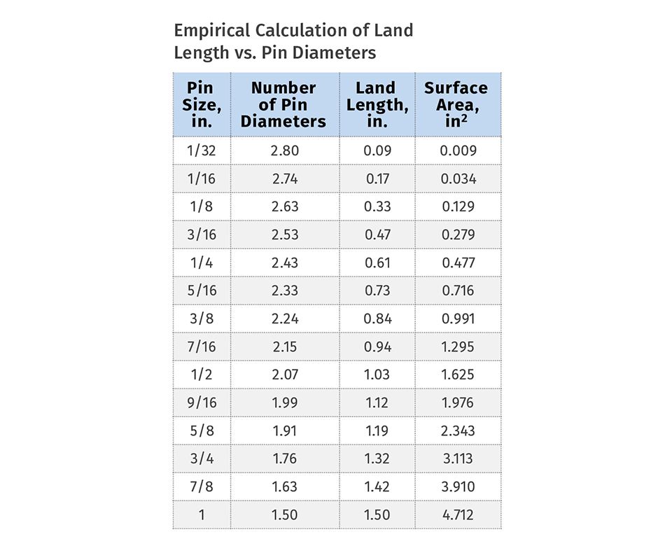
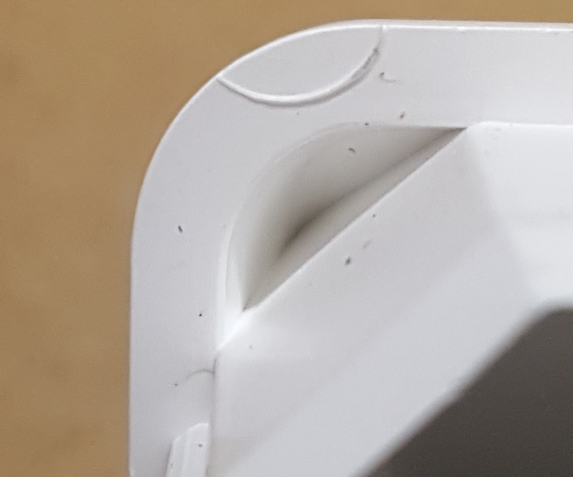
FIG 1 Example of a thumbnail ejector pin.
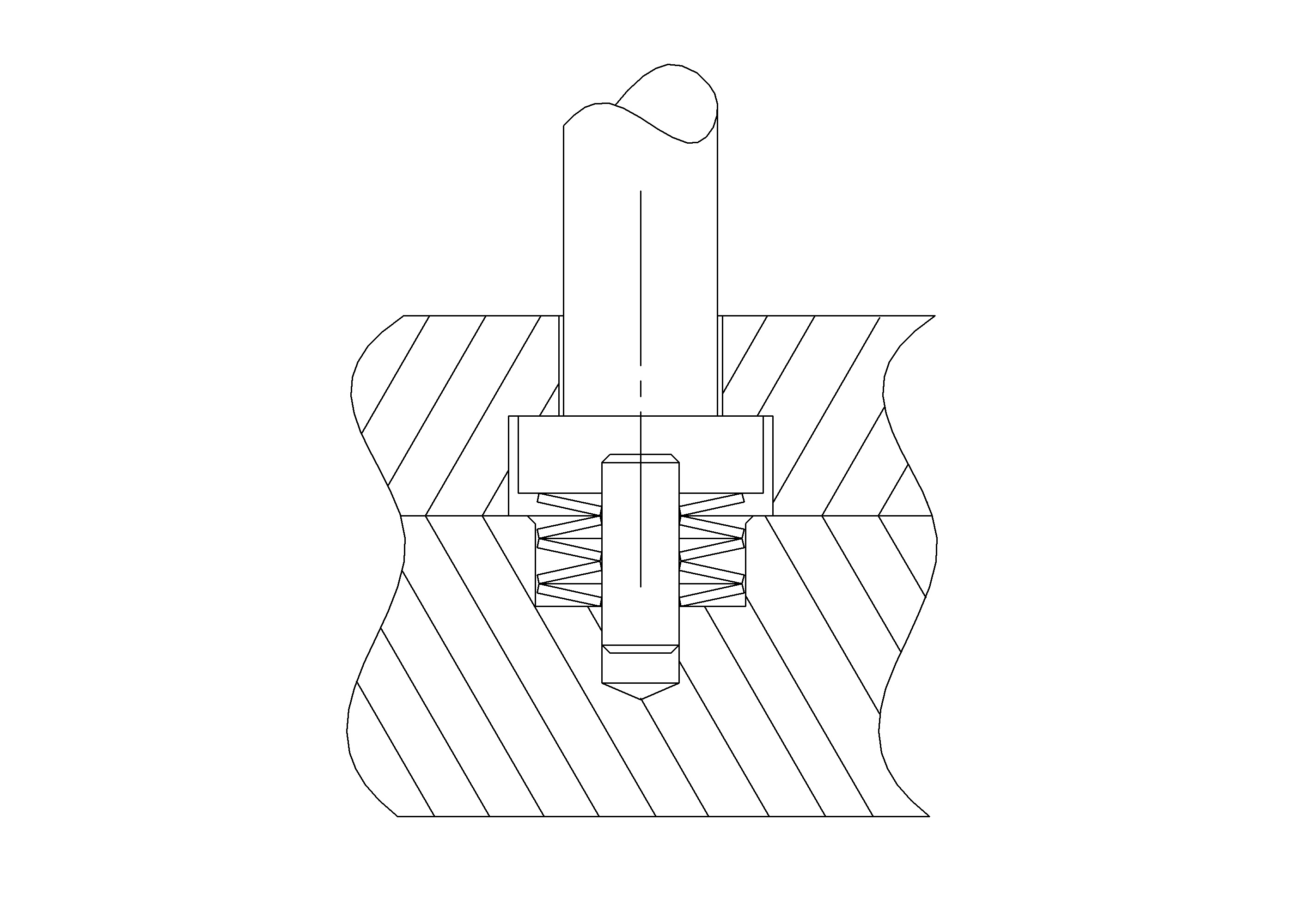
FIG 2 Bellville springs absorb impact and prevent damage in metal-to-metal applications.
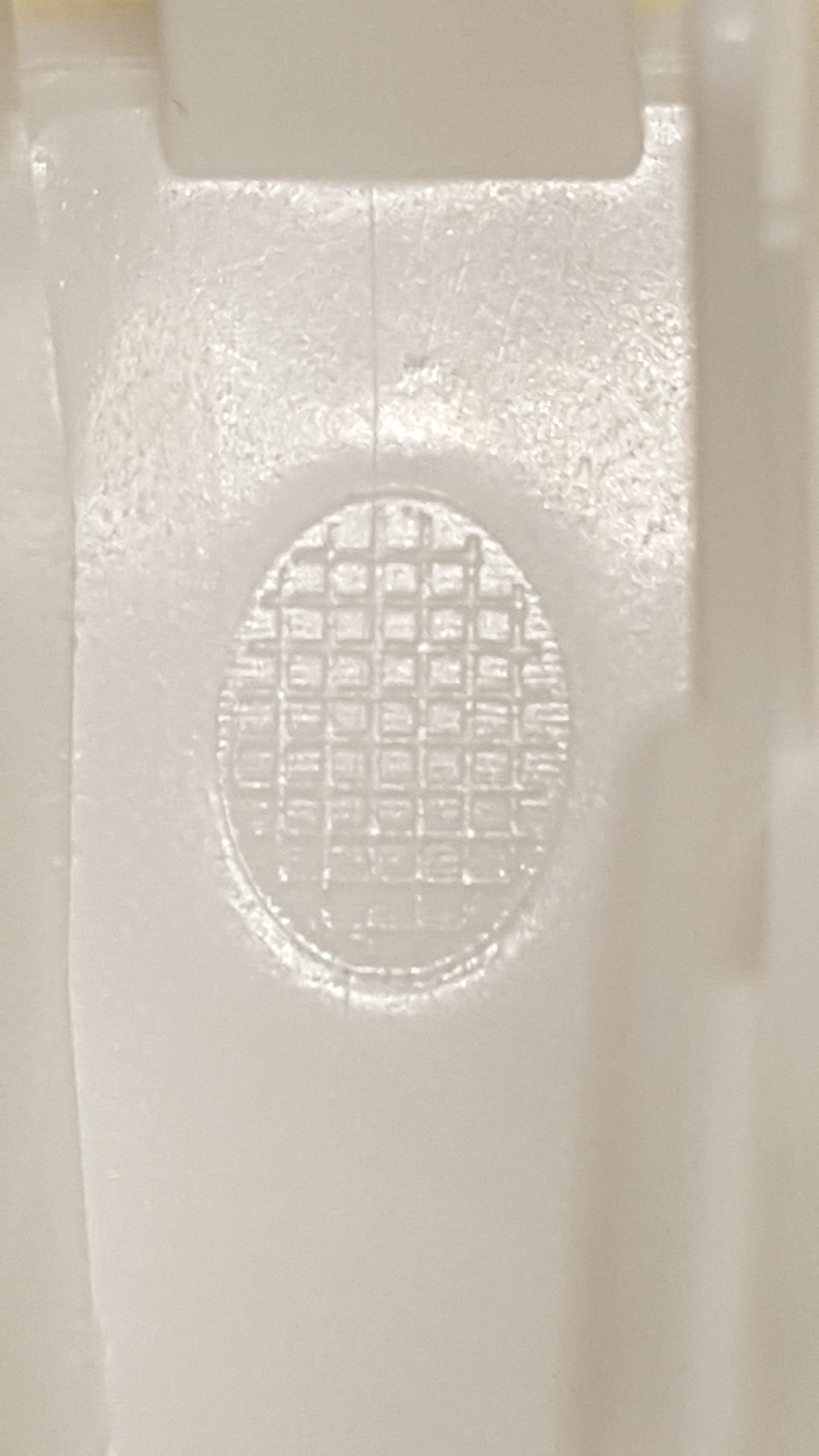
FIG 3 (L. to R.) Cross-hatched, partial and full stair-stepped ejector-pin faces. Notice the down-flash primarily on one side of the partial stepped pin.
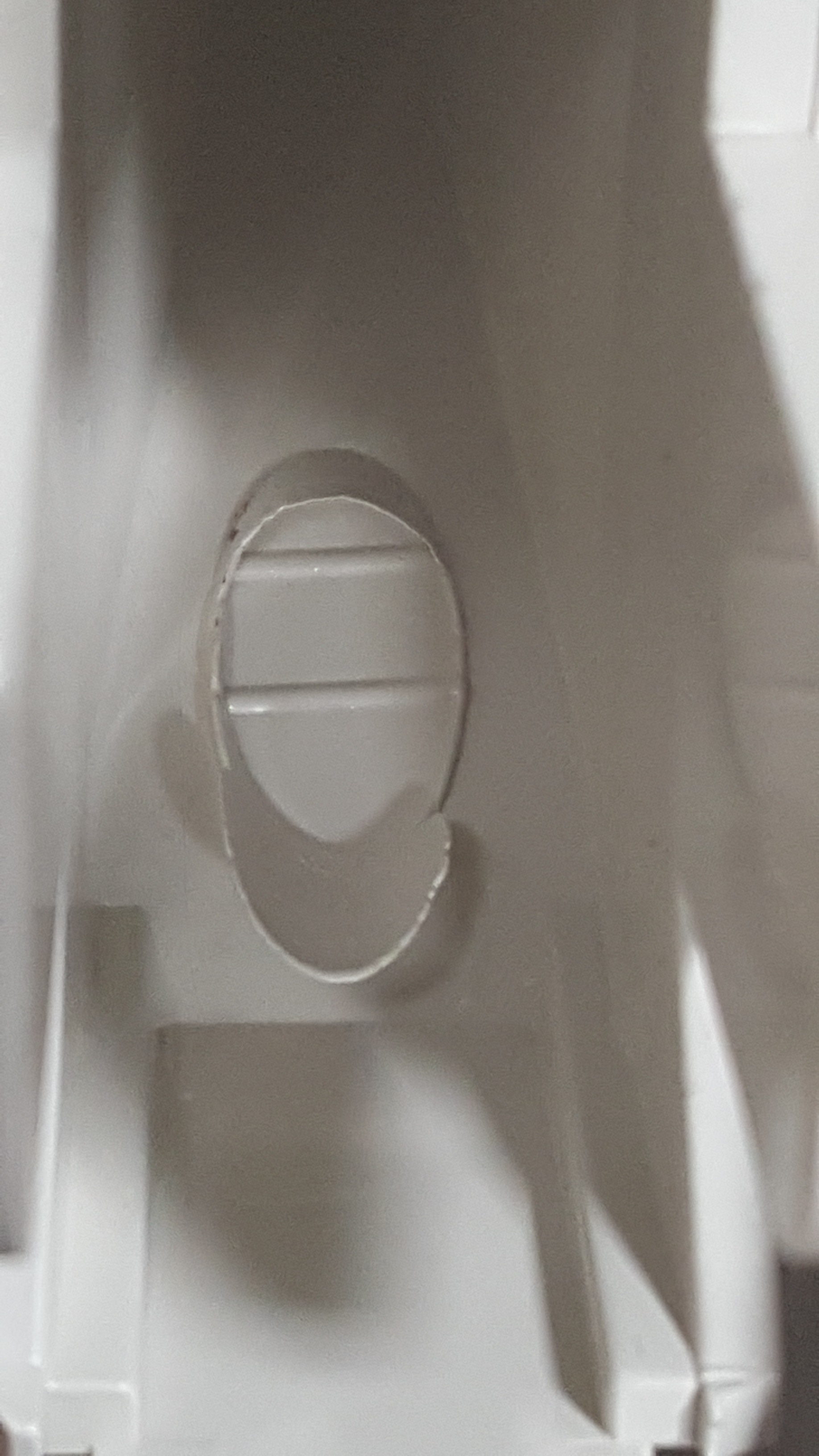
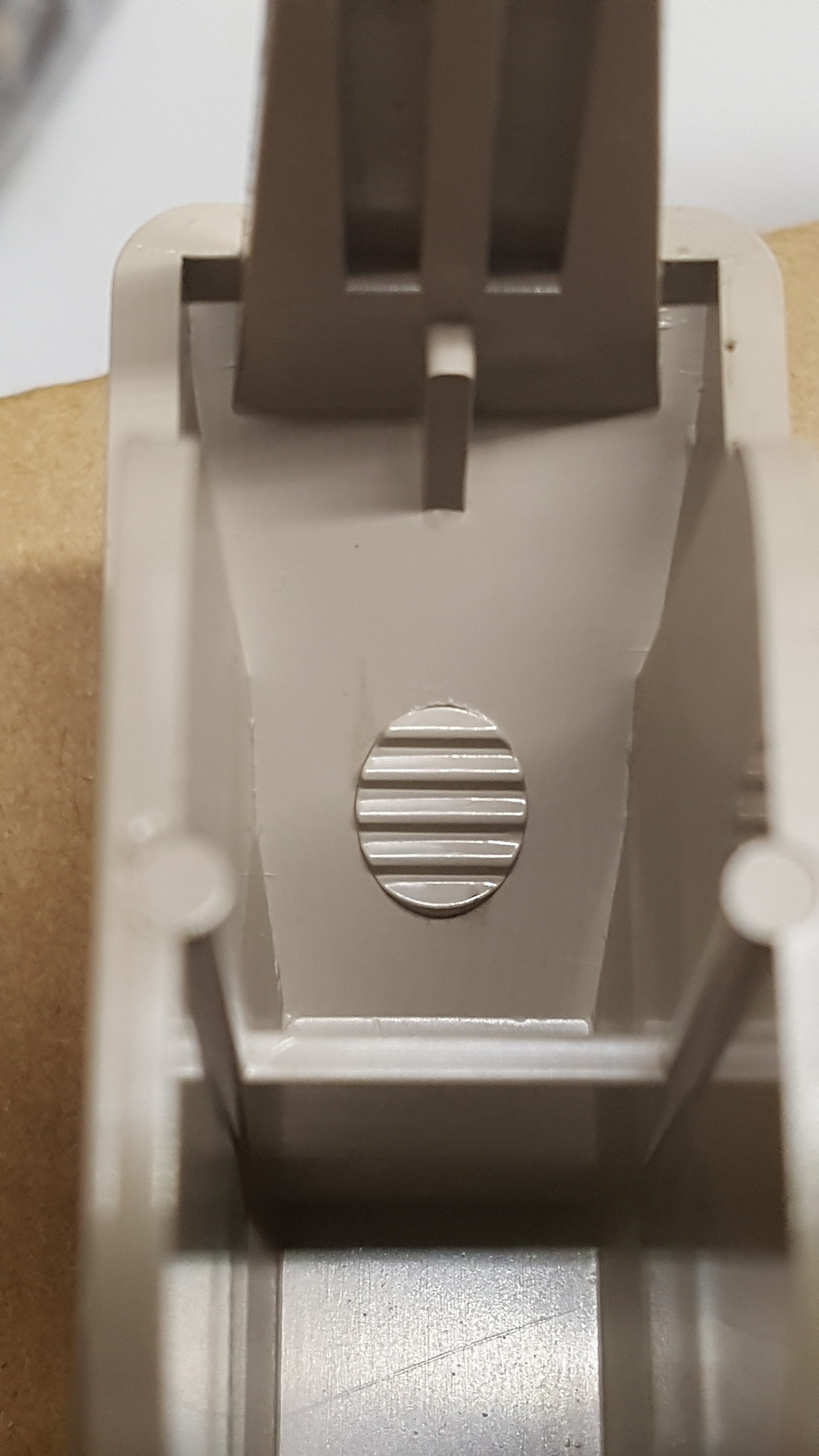
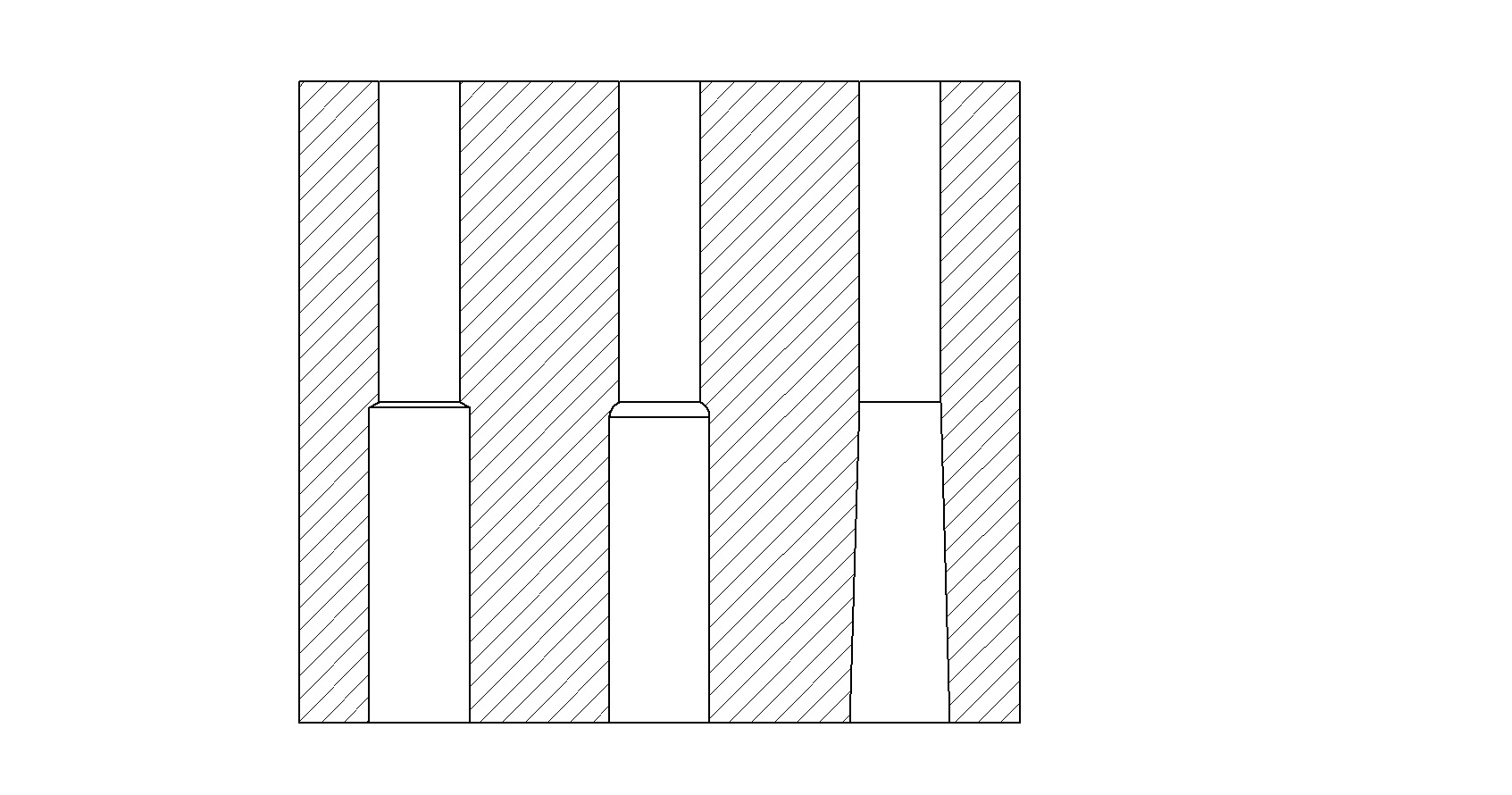
FIG 4 Clearance holes installed with (l. t r.) a drill bit, ball end mill and tapered reamer or wire EDM.


I spent a lot of time researching how much land or bearing length should be used in a core for various sizes of ejector pins. All I was able to find were several ambiguous rules of thumb. Some say the land length should be two times the pin diameter for pins under ¼ in. and one and a half times the pin diameter for pins over ¼ in. Others say the land length should be between ¾ in. and 1.5 in. Several sources say small-diameter pins need a “lot” of land length.
All of these “rules” seem far too general to me. And the rule about needing a long land for a small-diameter pin seems to me to be an incorrect conclusion as a result of an unsupported length issue. So I started to think about the pros and cons of various land lengths, or as my father used to say, “Think in terms of extremes.”
If a land length is excessively long, it would cause greater resistance for air and gas to vent out. And because of the increased surface contact area, it would generate a proportionally larger amount of frictional heat and abrasive wear, which could cause a pin to gall. Conversely, if a land length was excessively short, it could prematurely distort the hole in the core because of insufficient bearing surface to resist the forces of pin deflection, misalignment, and the associated side loads. There must be a logical, mathematical solution to this age-old conundrum.
A THOUGHT EXPERIMENT
I decided to make a chart starting with a 1-in. diam. pin and assigning it a land length of 1.5 times its diameter. I then incrementally increased the number of diameters by 1% until I reached the smallest standard diameter pin—1/32 in. Interestingly, even though the number of diameters increased, the land length and the amount of surface area decreased, as I suspected would be the case. The accompanying table lists the results of these calculations. I’m not recommending you use these values. They have yet to be validated. But you definitely should consider an ejector pin’s land length and the resulting amount of surface area, instead of arbitrarily using some rule of thumb that has little or no empirical validity or is based on incorrect assumptions from previous failures.
Since there is an exception to every rule, always leave a considerable amount of land length for any pin that ejects the sprue puller, runner, or various types of gates. As mentioned in a previous column, long bosses are often required in order for them to perform their intended function. If there isn’t enough land length to extend the length of a boss, that’s going to turn an easy fix into an expensive one.
If it ever comes down to having to make a choice between increasing the bearing length or accepting an excessive unsupported length—increase the bearing length. Theoretically, if all of the holes are perfectly aligned and there are proper clearances, you should not get any friction between the pin and the core. But that is in a perfect world—one without temperature variations, material outgassing, injection forces and machining tolerances. As a precaution, molds with very small ejector pins, or a lot of ejector pins, should initially have a short preventive-maintenance interval. Once some history has been established, the interval can be adjusted accordingly.
While the table lists the standard ejector-pin sizes, pins are readily available in 0.005-in. over-size diameters. If you shop around, you will find pins are also available in diameters as small as 0.010 in. and in increments of 0.0001 in. If you can’t find the exact size pin you need for a application, you can also consider using a metric pin. Whenever an odd-sized ejector pin is used, it should be engraved or otherwise marked to avoid mistakes during assembly. One trick is to coat the head of the pin and a portion of the retainer plate with a thin layer of metal stain.
It’s good practice to number every ejector pin—even if they are not keyed, or don’t vary in size or length. I once had preventive maintenance performed on a mold that ran a low-viscosity material—nylon 66. It just needed a good cleaning and some fresh grease. There was nothing wrong with the mold or the parts it produced. After the PM was performed, we developed flash running down several of the ejector pins and couldn’t figure out why. It turned out that the diameters of some of the pins were on the low side of their tolerance, and they were installed in some through holes that were on the high side of their tolerance. The tolerance stack-up was enough to cause a problem for a material that flashes at a clearance of just over 0.0005 in.
For molds running a low-viscosity material, each ejector pin should be measured individually to four decimal places, as well as the holes in the cores they go into. Keep in mind that an ejector pin never stays perfectly in the center of its hole. It will always shift to one side or the other. For this reason, I recommend that the amount of clearance between the hole in the core and the ejector pin should be slightly less than the vent depth recommended by the material manufacturer, but not too much less. A tight fit is one of the biggest reasons why an ejector pin will gall.
In extremely precise molds, the backs of the heads of the ejector pins should be ground so that they are all the exact same thickness, and perfectly perpendicular to the centerline of the pin and the direction of travel. This eliminates the chance of a lateral force being applied to the pin and the through-hole in the core, which can cause several different problems.
SLEEVE EJECTORS, TOO
Trying not to stray too far off topic, land-length consideration also applies when you are using a sleeve ejector—both on the outside diameter and the inside diameter. The bearing length on the OD is the same as you would use for an ejector pin of that diameter. The bearing length on the ID is a completely different story. The tip of the core pin inside the sleeve should never disengage from the sleeve’s internal land, or bearing length, regardless of how generous the lead-in angle might be—typically 1° per side. Therefore, a sleeve’s internal land length should be equal to the ejector stroke plus at least an additional 1/8 in. Otherwise, the tip of the core pin can wear as it rubs against the transition section.
The transition section is the area between the relief diameter and the land diameter. While this may seem like an excessive amount of bearing length, you must consider that the internal bearing length decreases as the sleeve advances to eject the part. Typical internal bearing lengths for standard ejector sleeves are 1.75 in. and 2.25 or 2.5 in. Nine times out of 10, the sleeve needs to be shortened to a required length. This reduces the bearing length. For long-running molds, custom sleeves with an increased bearing length may be warranted. If the ejection system isn’t guided and you have an ejector sleeve, add at least two dowel pins in opposing corners connecting the ejector plate and the ejector retainer plate to ensure they are properly aligned. This is also a good idea whenever a component such as a lifter is mounted in the ejector plate.
Some ejector pins must have their position oriented due to a shape or contour machined on their tip. There are several ways to do this. What’s important is that when you key an ejector pin, you usually lose lateral float in at least one direction. Therefore, these pins require greater positional accuracy. There is an advantage to keying ejector pins. They remain angularly oriented to any uneven wear on the pin and in the corresponding through-holes in the core. This is especially important when a portion of the pin butts up against plastic, and the remaining portion butts up against steel—as is the case with parting-line, “thumbnail,” or “toenail” ejector pins. Thumbnail ejector pins (Fig. 1) are a great way to prevent having to use small-diameter pins.
For example, instead of using a 1/64-in. diam. pin in the center of an 0.080-in. outside wall of a part, you can use a 1/8-in. diam. pin and let most of the pin extend beyond the edge of the part and seal off against the cavity. Not only will the larger pin have less chance of buckling, there is an increased amount of surface area pushing against the part. But there is a significant risk to this ejection method—one that I always try to avoid. If the pin is not perfectly flush or slightly below the parting line, the pin will indent the cavity plate or deform a portion of the face of the pin. If that pin isn’t keyed and can rotate, it’s going to flash parallel with the parting line. If you ever get this condition, don’t try to fix it by pre-loading the pin. That will eventually make the situation worse.
Any ejector pin that shuts off against steel should be through hardened—not nitrided. Nitriding is a surface or “case” hardening process, where the surface is typically between 65 and 74 Rockwell C. This high hardness diminishes gradually to a depth of 0.012 to 0.020 in. Due to the high surface hardness and softer center, nitrided pins can chip when they shut off against steel. Through-hardened pins made from M-2 steel at 60 to 63 Rockwell C are probably the best for steel-on-steel applications.
Be careful of pins that are labeled as being through hardened. Some can be much softer than M-2 pins and have an even softer center. There is one concern when using M-2 pins, however. They are rather brittle when it comes to withstanding side-load impact. I’ve seen parts hit and break small M-2 pins as the parts were falling out of the mold. Granted, parts should not hit ejector pins on their way out, but it gives you an indication of just how fragile small-diameter pins can be when it comes to side loads.
To avoid chipping or other damage to any type of pin that butts up or seals off against anything other than plastic, I like to add small Bellville washers, also known as a disc springs, under the head of the pin (Fig 2). The spring absorbs the impact and compensates for any change in length, which could otherwise cause flash to develop from a small gap or cause the head of the pin to mushroom from repeated compression. If the ejector plates are not tied into the molding machine and they are not spring loaded, this Bellville washer design works extremely well for preventing damage to return pins, which in this scenario is the only means of positive ejector-plate return.
A pin that is shaped or contoured with a steep angle usually wears out the through-hole in the core on the side opposite the contoured shape, due to the tangential forces applied during both injection and ejection. This is why contoured pins will develop “down-flash” before non-contoured pins will. To help reduce this accelerated wear, the face of the contoured pin should have a stair-stepped relief, often referred to as “teeth.” This won’t keep the pin from being pushed to the side by plastic pressure, but it greatly reduces the tangential forces during ejection. Instead of stair-stepping, some mold makers use a coarse EDM finish, a cross-hatched pattern, or simply a few notches on the face of the pin to get a better grip on the part.
None of these methods are as effective as a full stair-step design (Fig 3). It is often a good idea to install a shaped pin in a fixed sleeve. If the sleeve wears out, it is easier and cheaper to replace it than having to repair a worn through-hole in the core. Having an ejector pin ride in a fixed sleeve is also ideal if the core is relatively soft, or if the molding material is corrosive. If a shaped ejector pin needs to have its face polished, it should be made of through-hardened steel to prevent “dishing” in the softer center during polishing.
From time to time, a threaded hole has to be added to the face of a large ejector pin or return pin. One common example is when two ejector pins are connected to a bar, and the bar ejects the part. Another example is when an ejector system is spring loaded. Trying to assemble the mold without damaging the ejector pins can be very difficult because of the necessary pre-load. Adding a tapped hole on the end of the return pins and installing a screw and washer keeps the ejector retainer plate in the perfect position for assembly. In order to tap the end of these pins, you either need a nitrided pin, which has a core hardness of 40 to 50 Rockwell C, or an equally soft through-hardened pin.
Ejector-pin clearance, or relief holes, are drilled into the back of the support plate and frequently into a portion of the core insert. The clearance depth in the core insert ends at the beginning of the land or bearing diameter. The diameter of these clearance holes is typically 1/32 in. larger than the nominal ejector-pin diameter. That might be fine for larger pins; but for smaller pins, especially any shouldered pins, it is better to reduce this clearance to just 1/64 in.—the same amount that should be used in the ejector retainer plate. The pins will be allowed to bend only about 0.008 in. before the inside diameter of the bore supports the pin and prevents it from bending any further. And yes, when a pin bends and comes in contact with the side wall of a clearance hole, it effectively reduces its unsupported length, which is advantageous for reducing the chances of it buckling and breaking.
There is a transition section between the clearance hole and the land area in the core. It is formed by the angle on the tip of the drill bit—typically 118° or 135°. While it’s not usually necessary, it is good practice to blend the sharp edges at the beginning and end of the transition. Using a ball mill instead of a drill bit helps, but a tapered reamer is considerably better. This prevents the tip of the pin from chipping during assembly—especially if the pin has a texture, engraving, or a contoured shape on the end. Note: When engraving an ejector pin or core pin with a cavity number or other indicia, stay at least 0.020 in. away from the perimeter, especially if the pin is nitrided. If the engraving is too close to the edge of the pin, the pin becomes extremely weak and fragile.
If a mold has interchangeable cores and they are “face” or parting-line mounted, the relief holes for the ejector pins should be reamed with a full taper from the back face of the core to the start of the land diameter. Sometimes it’s possible to wire-EDM this taper (Fig. 4). This makes it much easier to align the ejector pins to the land diameter without damaging the pins during the changeover assembly.
Since ejector pins need to be cut to a precise length, care should be taken to remove any small burrs on the tip of the pin. If you are super meticulous and don’t like the aesthetics of the heat-induced blue color on the end of a pin, there are various chemicals available to safely remove it. Several toilet-bowl cleaners work just as well at a fraction of the price.
It is not uncommon for the diameter of a boss on a part, or especially on a runner, to be exactly the same as the ejector pin’s land diameter. In cases such as this, take a polishing stone and break the edge of the perimeter of the ejector pin—just enough to prevent the sharp edge from digging into the sidewall of the core. A better idea is to make the diameter of the boss at least 0.010 in. larger than the ejector pin. This will also help prevent down-flash as the pin begins to wear or corrode.
HOW TO MACHINE EJECTOR-PIN HOLES
Let me briefly discuss the various methods used to install holes for ejector pins. First, every plate must be ground flat and machined perfectly square before any other machining can be performed. Years ago, plates were stacked together and the larger holes for leader pins, return pins and guide pins were “line bored” to ensure proper hole alignment. With today’s precision CNC machines, line boring is no longer necessary. Typical positional accuracy is easily ±0.001 in. but can be much finer if the edges of the mold plates are ground smooth. This gives a more precise indicator reading when setting up the plates in the mill.
Some tool makers like to install all the ejector-pin holes from the front of the core, before the shape of the core is machined. While this will give you excellent positional accuracy, it makes milling precarious because of all the interrupted cuts. That may be acceptable for soft materials, such as aluminum, but you risk breaking cutters on tool steel. You also never want to install ejector pins to size, prior to heat treating. Heat treating can cause the steel to “grow” or warp, which will change the locations of the holes.
Drilling ejector-pin holes from the front leaves a small chamfer, or bell mouth, on the surface. Therefore, never drill from the front unless there is extra stock on the core, which will be removed later. However, if the core is fairly thick or made of pre-hardened steel, and the pin diameter is small, there is the risk that the drill bit will “drift,” “walk” or wander out of position as it cuts. In this case, you can drill a smaller-diameter hole from the front, then drill and ream it to the final size from the back. Drilling from the back will leave a slight burr when you break through the front, but it can easily be stoned off. Don’t forget to add a countersink to the clearance holes at the back of the core and the back of the support plate to provide a lead-in for the pins.
It all comes down to this: Molds are expensive, but so is downtime. You have to find a happy balance between how many expensive extra steps to take in the mold design and mold construction, versus the risks and costs associated with mold repairs during its lifespan, as well as not being able to meet your customer’s production requirements.


Related Content

Improve The Cooling Performance Of Your Molds
Need to figure out your mold-cooling energy requirements for the various polymers you run? What about sizing cooling circuits so they provide adequate cooling capacity? Learn the tricks of the trade here.
Read More
How to Optimize Pack & Hold Times for Hot-Runner & Valve-Gated Molds
Applying a scientific method to what is typically a trial-and-error process. Part 2 of 2.
Read More
How to Start a Hot-Runner Mold That Has No Tip Insulators
Here's a method to assist with efficient dark-to-light color changes on hot-runner systems that are hot-tipped.
Read More
What You Need to Know About Leader Pins and Bushings
There’s a lot more to these humble but essential mold components than you might suspect. Following the author’s tips could save much time, money and frustration.
Read MoreRead Next

Understanding Melting in Single-Screw Extruders
You can better visualize the melting process by “flipping” the observation point so that the barrel appears to be turning clockwise around a stationary screw.
Read More
Processor Turns to AI to Help Keep Machines Humming
At captive processor McConkey, a new generation of artificial intelligence models, highlighted by ChatGPT, is helping it wade through the shortage of skilled labor and keep its production lines churning out good parts.
Read More
Troubleshooting Screw and Barrel Wear in Extrusion
Extruder screws and barrels will wear over time. If you are seeing a reduction in specific rate and higher discharge temperatures, wear is the likely culprit.
Read More