
Injection Molding: Better Flow Simulation with Fiber Reinforcements
Long and short fibers align during flow in the mold, and this, in turn, influences the flow pattern. New math helps Moldex3D simulate this phenomenon.


CoreTech System Co., supplier of Moldex3D flow-simulation software, says it has increased the accuracy of injection molding and compression molding simulation with long- and short-fiber reinforced thermoplastics. The problem, according to CoreTech, is that flow-induced orientation of the fibers in turn causes anisotropic flow of the melt in the mold. “So far, simulating such a fiber-orientation-induced anisotropic flow has still been a challenge for state-of-the-art CFD (computational fluid dynamics) software,” says Dr. Huan-Chang (Ivor) Tseng, R&D program manager at CoreTech.
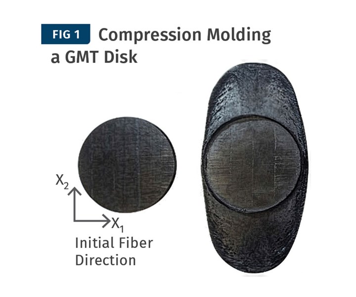
During compression molding, a circular disk of GMT shows an elliptical, rather than circular, flow pattern, due to glass orientation.
This anistropic flow can be observed by placing a circular “hocky puck” charge of glass-mat thermoplastic (GMT) sheet in a compression mold (Fig. 1). The circular disk deforms into an elliptical shape as it flows. In injection molding, unreinforced plastics typically show a smooth, continuous flow front (Fig. 2, top); but Dr. Tseng says, “Some peculiar, irregular filling patterns are known to occur for high concentrations of short or long fibers” (Fig. 2, bottom). These patterns show the flow front advancing faster along the sidewalls of the cavity than in the center.


Injection molding of unreinforced thermoplastic (A) shows a uniform flow front. With glass fibers (B), their orientation causes anisotropic flow, which proceeds faster along the walls than in the center.
CoreTech says it has overcome this challenge by incorporating the informed-isotropic (IISO) viscosity model developed by Dr. Anthony J. Favaloro and Prof. R. Byron Pipes at the Composites Manufacturing and Simulation Center of Purdue Univ. The details of the IISO model recently were disclosed in U.S. patents and published in scientific journals.

Incorporating the IISO viscosity model helps Moldex3D to predict the elliptical flow of a circular charge of long-glass PP in compression molding.
Using this model, CoreTech’s Moldex3D simulated compression molding of PP with 25% long glass in a unidirectional orientation. The simulation correctly predicted an ellipse developing from the original circular charge (Fig. 3). For 50% short glass in nylon 66, Moldex3D simulated an injection molding flow front advancing faster along the side walls than in the center (Fig. 4).

IISO viscosity model in Moldex3D also correctly predicts anisotropic flow in injection molding glass-filled nylon 66, with faster flow along the sidewalls than in the center.
The new “fiber coupling” function is incorporated in the current Moldex3D R17 version and in the new Moldex3D 2020 version, which adds the ability to see how changing the fiber length and concentration will affect the filling pattern.
Related Content
-
Know Your Options in Injection Machine Nozzles
Improvements in nozzle design in recent years overcome some of the limitations of previous filter, mixing, and shut-off nozzles.
-
What to Do About Weak Weld Lines
Weld or knit lines are perhaps the most common and difficult injection molding defect to eliminate.
-
How to Optimize Pack & Hold Times for Hot-Runner & Valve-Gated Molds
Applying a scientific method to what is typically a trial-and-error process. Part 2 of 2.


