
Conformal Cooling Helps Get Heat Out and Cycle Time Down
Conformally cooled sprue bushings help automotive molder reduce cycle times and injection pressures for a high-volume component.

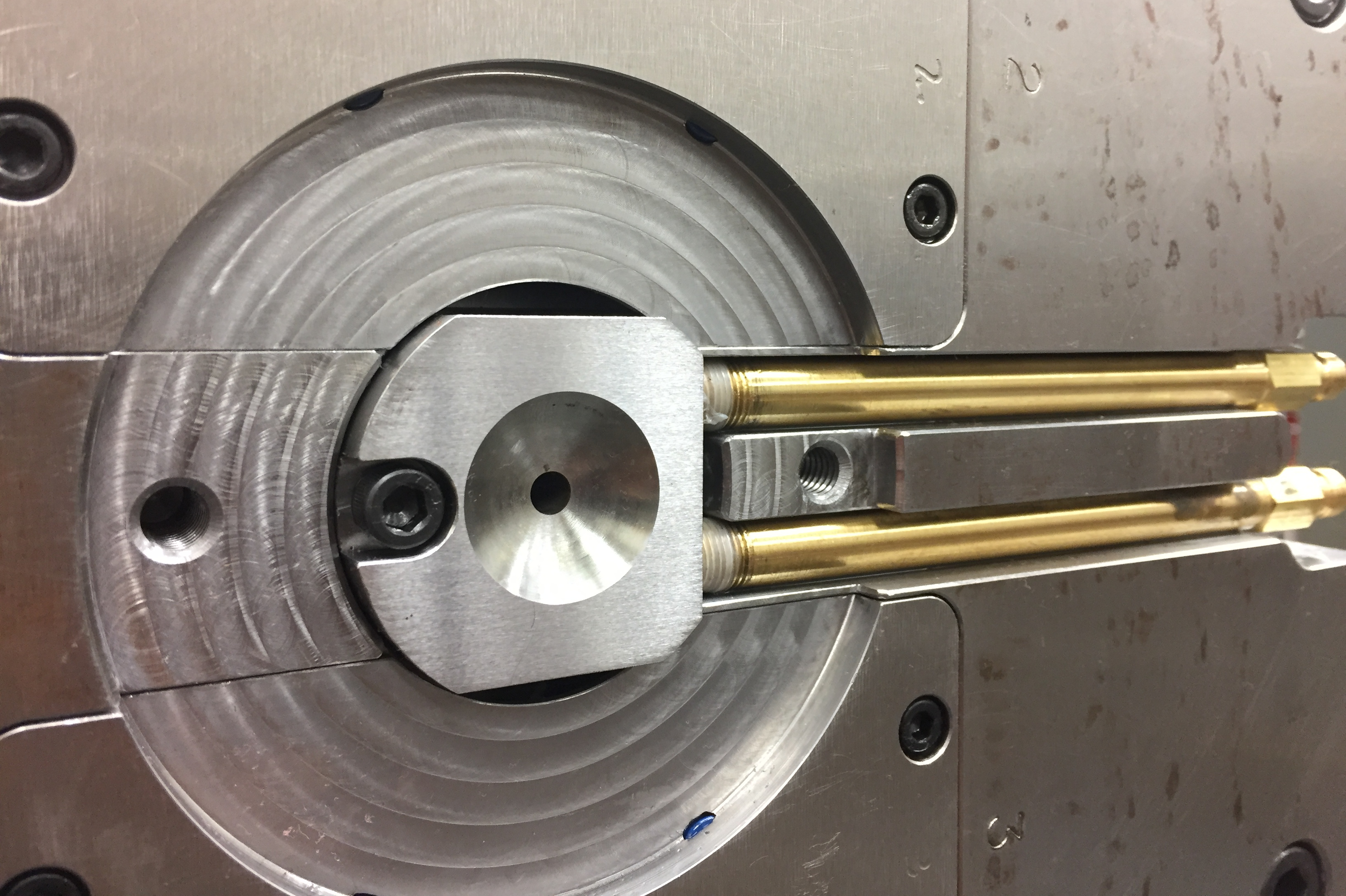
Showing the system as installed with the locating ring removed for more visibility, the picture displays the water inlet and outlet lines coming in from the side of the tool and connecting at the base of the conformally cooled sprue bushing.
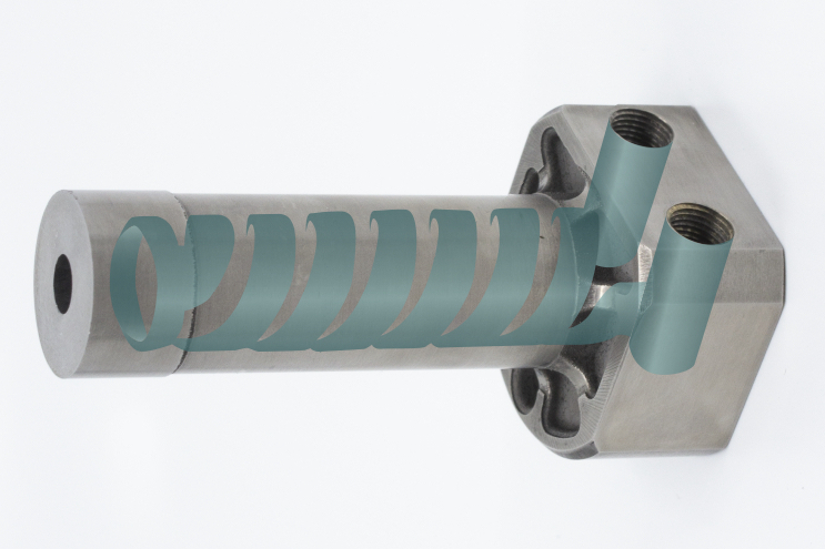
New conformally cooled sprue bushing from PCS (patent pending) encircles the melt channel with a 1/8-in. water line.


Custom molder ITW Deltar Fasteners, Chippewa Falls, Wis., faced a unique challenge with a high-volume acetal fastener. Achieving a quality surface finish required using faster injection speeds, but those speeds also pushed pressures higher in what was already a pressure-limited process.
“It seemed that anything we tried to do to reduce the pressure—open the sprue, open up the runner, increase the temperature—would have a negative impact to the cycle,” explains Brock Cooley, tooling engineer at ITW Deltar Fasteners. “So we had to try to find that fine line and balance to achieve the optimum process.”


Cooley posed this process challenge to Scott Wahl of mold-component supplier PCS Company, Fraser, Mich., and Wahl saw an opportunity to pitch a new product borne of a new collaboration. PCS had recently begun working with Jason Murphy, president of Next Chapter Manufacturing (NXCMFG; Grand Rapids, Mich.) a toolmaker that applies additive manufacturing technologies. PCS was working with NXCMFG on mold components that utilize 3D printing, and one of the first developments to come from that partnership was a sprue bushing featuring a conformal cooling channel.
That product, which comes in 10 sizes, features a patent-pending design that maximizes the surface area of a 1/8-in. water line. Squeezed into a “kidney shape,” according to Murphy, the cooling line forms a sort of double helix that wraps all the way around the sprue bushing, crossing at the top before coming back down and exiting at the bottom, with one water inlet and one outlet. The component is formed from H13 steel via direct metal laser sintering.
“Because it is a 1/8-in. water line it enables a higher level of flow,” Murphy says, “contrary to smaller, more restrictive lines.”
Prior to applying the conformally cooled sprue bushing, the eight-cavity fastener tool was running a 20.3-sec cycle at 22,500 psi. When the first iteration of the new sprue bushing was installed, those numbers dropped to 17.8 sec and 22,000 psi. When a duplicate mold for the part was made, a new sprue bushing was created and by tweaking the orifice size, the molder dropped the cycle time to 15.7 sec with a pressure of about 18,000 psi. “What the new bushing did was allow us to increase our nozzle size on the press but still have the sprue set up in time,” Cooley explains.
PCS and NXCMFG see big opportunities for the new sprue-bushing concept, especially where large sprues meet multiple small cavities.
“When you have small parts and multiple cavities,” Murphy says, “you have to start out with a very large sprue so that by the time you step down to the smallest cavities, you’re feeding them properly. With a larger sprue and small parts, your sprue is going to be the limiting factor in cycle time.”
Related Content
-
How to Select the Right Tool Steel for Mold Cavities
With cavity steel or alloy selection there are many variables that can dictate the best option.
-
How to Reduce Sinks in Injection Molding
Modifications to the common core pin can be a simple solution, but don’t expect all resins to behave the same. Gas assist is also worth a try.
-
Are Your Sprue or Parts Sticking? Here Are Some Solutions
When a sprue or part sticks, the result of trying to unstick it is often more scratches or undercuts, making the problem worse and the fix more costly. Here’s how to set up a proper procedure for this sticky wicket.


