
What You Should Know About Miniature Extrusion Screws
Very small screws have become more common with the growth of additive manufacturing. Designing such screws requires balancing their output requirements with their torque strength.
.jpg;width=70;height=70;mode=crop;format=webp)


To accept pellets or even ground pellets, the feed sections of very small screws need to be proportionally deeper—that is, with a greater compression ratio—to match the output of the rest of the screw. That is due to the restrictive entry dimensions into the screw and lower compaction rates resulting from far fewer particles in the screw channel. Increasing the channel depth in the feed section naturally lowers the torque capacity of the screw.
In additive manufacturing equipment there has been a migration away from heat guns, which feed polymer filaments to supply the melted polymer, to miniature extruders. Miniature extruders increase part buildup rates or output and reduce material cost. Due to the poor heat transfer of polymers, the output of heat guns is limited, and the cost of filament is typically five times or more the cost per pound of pellets. Design of miniature or very small screws, whether used for additive manufacturing equipment or not, requires balancing their output requirements with their torque strength.


For additive manufacturing extruders, this may be even more important, as many are not operated by typical extrusion processors, and cold starts are inevitable. In such applications the screw strength needs to exceed the full torque available from the drive, so that during a possible cold start, where the drive torque instantly jumps to the full drive capacity, the screw does not break.
Compared with heat guns, miniature extruders increase part buildup rates or output and reduce material cost.
There are relatively simple calculations, using well established mechanical engineering principles, to avoid screw breakage.
The available torque from the drive is calculated as:
Drive torque (in.-lb) = (Horsepower × 63025) ÷ Maximum screw speed
For example, I recently worked on an extruder having a 2-hp drive motor with 1750-rpm maximum speed, coupled to a 10:1 gear reducer, resulting in a maximum screw speed of 175 rpm.
Available torque = (2.0 x 63025) ÷ (1750/10) = 720 in.-lb of torque.
The screw torque is calculated as:
Screw torque = 16T/(πd3)
Torsional strength equals 16 times the available torque from the drive divided by πd3 where (d) is the root diameter of the screw in its deepest section closest to the drive, which is the feed section. An example is a 0.625-in. diam. screw with a 0.325-in. root diameter in the feed section.
Torque strength = (16 × 720) ÷ (π × (0.325)3) = 106,820 psi
Torsional strength varies from zero at the center of a shaft to a maximum at its outer most surface. That’s why a screw-torque failure initially shows cracks initiating from the flight O.D. extending toward the center. There are different shape factors for determining the torsional strength of common shapes (squares, rounds, triangles, etc.). These have been experimentally developed, but none exist for the cross-section of a screw. As a result, the round section of the screw root is typically used, even though it represents less than the total torsional strength.
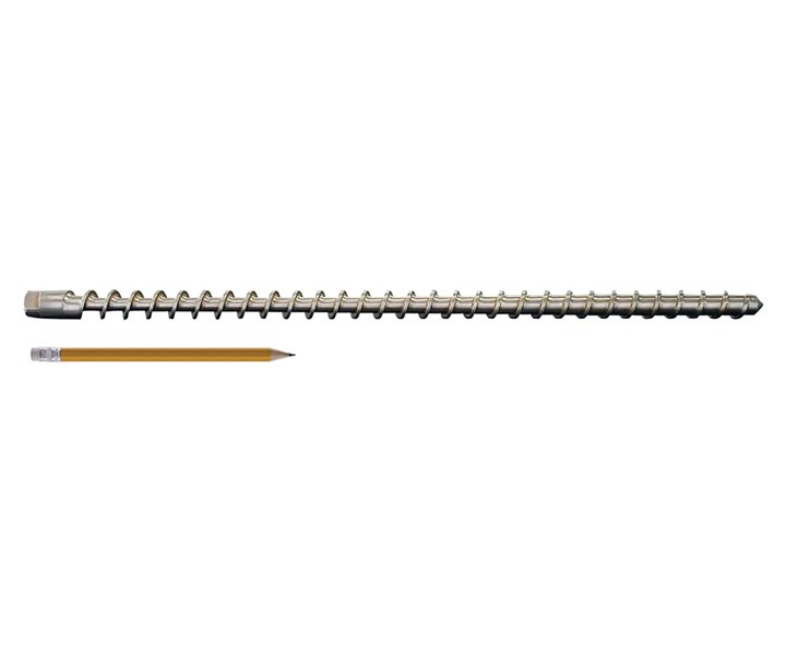 Tiny extruder screws (compared to pencil) figure to become more common as additive manufacturing expands. Shown here is a 5/8-in. diam. screw with an overall length of 16.28 in. Photo: Triex LLC-Filabot.
 Tensile strength of the typical steel for extrusion screws is 4140 steel heat-treated to 32 Rc hardness, which has a tensile strength of 145,000 psi. Shear strength for steels is conservatively specified as 0.577% of tensile strength, so allowable torsional stress is 83,655 psi, although the screw flight increases the strength an indeterminate amount.
That means that the feed section for the 5/8-in. screw noted above would be stressed to essentially 128% of maximum design strength at full drive load. To obtain the desired output, the depth of the screw would then have to be decreased and the maximum screw speed increased. Alternatively, a higher-strength steel such as H-13 could be used. At a hardness of Rc 52 its tensile strength is 289,000 psi and its torsional stress would be 166,753 psi or well above required strength. The H-13 tool steel was the solution chosen as the polymer was a copolyester with no corrosion issues.
About the Author: Jim Frankland is a mechanical engineer who has been involved in all types of extrusion processing for more than 40 years. He is now president of Frankland Plastics Consulting, LLC. Contact jim.frankland@comcast.net or (724) 651-9196.


Related Content

The Importance of Melt & Mold Temperature
Molders should realize how significantly process conditions can influence the final properties of the part.
Read More
Tunnel Gates for Mold Designers, Part 1
Of all the gate types, tunnel gates are the most misunderstood. Here’s what you need to know to choose the best design for your application.
Read More
The Strain Rate Effect
The rate of loading for a plastic material is a key component of how we perceive its performance.
Read More
Why (and What) You Need to Dry
Other than polyolefins, almost every other polymer exhibits some level of polarity and therefore can absorb a certain amount of moisture from the atmosphere. Here’s a look at some of these materials, and what needs to be done to dry them.
Read MoreRead Next

Beyond Prototypes: 8 Ways the Plastics Industry Is Using 3D Printing
Plastics processors are finding applications for 3D printing around the plant and across the supply chain. Here are 8 examples to look for at NPE2024.
Read More
Making the Circular Economy a Reality
Driven by brand owner demands and new worldwide legislation, the entire supply chain is working toward the shift to circularity, with some evidence the circular economy has already begun.
Read More
Lead the Conversation, Change the Conversation
Coverage of single-use plastics can be both misleading and demoralizing. Here are 10 tips for changing the perception of the plastics industry at your company and in your community.
Read More