
How to Prevent Nozzle Tip Leaks, Part 1
Instead of learning from your mistakes, stop making them in the first place.


In August I attended a three-day seminar in Ashland, Ohio on hot-runner systems given by MoldTrax. It was an excellent program, full of great information. Five leading hot-runner manufacturers spoke about their product offerings and key features of their systems. Steve Johnson, president of MoldTrax, reviewed how to correctly check and repair molds that had been flooded with plastic. Everyone was very impressed at the level of detail and the abundance of tricks Steve uses to bring a mold back to life. The amount of man-hours and replacement part costs required to repair a flooded mold are absolutely staggering.
The seminar reinforced my belief that we desire and need all of the latest technology—servomotor drives, sequential valve gates, smart controllers, thermal-imaging devices, etc. At the end of the seminar, Rich Oles, president of Alba Enterprises, showed us slide after slide after slide of flooded manifolds, and explained what happened in each instance. Watching Rich’s presentation reinforced my belief that there is a definite lack of understanding of some of the very basics of injection molding. These shortcomings are not limited to some of the personnel out on the production floor. It starts at the very top—with the suppliers of these hot-runner systems and the various mold components.


Several of the disasters in Rich’s slides were a result of material leaking out between the machine’s nozzle tip and the nozzle seat on the sprue bushing attached to the hot manifold. It caused a massive blob of plastic to form—often called a hog’s head. It had nothing to do with valve-pin wear, controller capability, or even the mold design and construction. This was a direct result of not knowing, not remembering, or not checking some critically important basics to running an injection mold, whether hot- or cold-runner.
Material leaking between the machine’s nozzle tip and the mold’s sprue bushing will immediately make your parts lighter, full of sinks, or even short. This is a big red flag. Monitoring part weight is the best indicator of the stability of your process and the possibility of a leak somewhere in the melt-delivery system. The most common knee-jerk reaction is to increase the shot size or the melt temperatures. Both of these actions only make the situation worse—for both hot- and cold-runner molds.
Depending on the design of your hot-runner system, there may or may not be a gap between the inside diameter of the locating ring and the outside diameter of the sprue bushing. If there is, it’s an invitation for material to enter the manifold housing. This open area needs to be sealed off. Some mold makers use a cylindrical piece of pipe, often called a “splash ring.” Others use a flat disk mounted underneath the locating ring, with a hole in the center to allow the sprue bushing to slide through. This is similar to those fiberglass “drool disks” one mold-component supplier sells to prevent leaking material from working its way back onto the barrel’s heater-band wires—only in reverse. Preventing material from entering the hot-runner manifold is critical, but why is there material leaking between the machine nozzle tip and the sprue bushing in the first place?
Any a gap between the locating ring and the sprue bushing needs to be sealed off.
The most common root cause for material leaking in this area is barrel misalignment. This condition takes only a few seconds to check. Pull the carriage back and then bring it forward again. If you can see it hop up, down, left or right, it’s misaligned—by a lot. In addition to potentially causing material to squirt out, misalignment will damage the face of your nozzle tip and the sprue-bushing seat. I’ve seen barrels so badly misaligned, the nozzle tips didn’t even touch the nozzle seat. They slammed into the locating ring.
The most common root cause for material leaking in this area is barrel misalignment.
Aligning an Injection Carriage
So how do you align an injection carriage? Most people do it by eye with a mold in the machine. Others use a piece of cardboard or pressure-sensitive film—again with a mold in the machine. They look at the compressed area to see which direction needs to be adjusted. Cardboard and film are actually better methods then sighting it by eye, but all of them are still extremely inaccurate.
A locating ring has a specified diameter of 3.990 in. I could not find a single supplier that specified what the tolerance of that dimension is. The through hole in a machine’s fixed platen is typically 4.000 +0.002/-0.000 in. Therefore, a new mold in a new machine can have as much as 0.010 in. of slop between them—in any direction. If your mold-component supplier is not keeping pace with technology, I recommend you make your own locating rings with a larger diameter. A diameter of 3.995 in. cuts the amount of slop in half. If it doesn’t fit the through hole in your platen—the protruding dings in the hole need to be stoned off.
Think about this for a second. You just hung a multi-cavity hot-runner mold in a high-precision all-electric molding machine. You know you have about 0.010 in. of slop between the locating ring and the hole in the platen, and now you are relying on a safety-glass-wearing floor person’s eyesight, or the visual inspection of a piece of cardboard to prevent molten material from entering your manifold system.
Fortunately, there is a better way: Make a barrel-alignment mandrel. Turn down a bar of steel to a diameter of 3.999 in. and add a lead-in on one end. Now drill a hole in the center, which will have a slip fit for a custom shoulder bolt with a 7/8-14 thread—or whatever thread size is in your machine’s nozzle body. Remove the machine nozzle tip from the nozzle body and screw the mandrel onto the end, as shown in Fig. 1. Remove any mold that may be in the machine. Loosen the carriage leveling bolts and advance the carriage until the mandrel is well inside the platen, as shown in Fig. 2. Now adjust and tighten the carriage leveling bolts. The carriage is now aligned with the center of the fixed platen within 0.0005 in., a minimum of 20 times more accurate than the way you are doing it now.
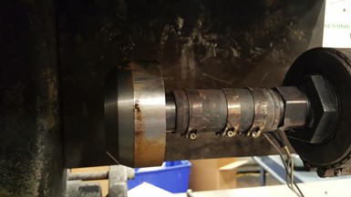
FIG 1 Barrel-alignment mandrel shown here on a nozzle body.
Just about everyone in our industry talks about how important the melt-delivery system is—from the material hopper to the end of fill. Believe it when I tell you that the most misunderstood, and often the weakest link in this melt-delivery chain is the machine nozzle tip. The rest of this article and all of next month’s article will explain why.

FIG 2 Barrel-alignment mandrel shown here inside a platen.
Many people believe that if the nozzle-tip orifice is too small it can cause the carriage to blow back because there is more steel surface area for the plastic pressure to push against. That’s not correct. It doesn’t matter if the nozzle tip orifice is just a pinhole, or if it is the same size as the sprue-bushing orifice. Consider that every piece of steel, from the shutoff nozzle in the barrel all the way to the end of the cavity, is a pressure vessel with various diameters and shapes. The pressure trying to separate the nozzle tip from the sprue bushing is applied to both the steel and the plastic. If you want a close approximation of how much force is trying to push the carriage back, take the peak injection pressure and divide it by the area of the largest orifice.
When the orifice of a machine’s nozzle tip is too small, it creates several problems. It will take more pressure to get the material to flow through the smaller diameter than it would a larger diameter. It’s better to use that lost pressure to pack out your parts, as opposed to needlessly increasing your electric bill. A small orifice also increases the shear on the material, which raises the temperature of the melt and reduces it’s viscosity. Would you rather control the temperature of your material with your screw and heater bands, or with a restrictive nozzle tip? (That is a rhetorical question.)
This reminds me of something. One reputable hot-runner manufacturer uses a smaller orifice diameter in its sprue bushings, which then feeds into a larger-diameter flow channel. I always thought that was a bad idea, because of the increased shear on the material. Perhaps this is intentional so that the amount of force trying to blow the carriage back is reduced. That’s an interesting tradeoff and something to keep in mind if you ever need a Plan B.
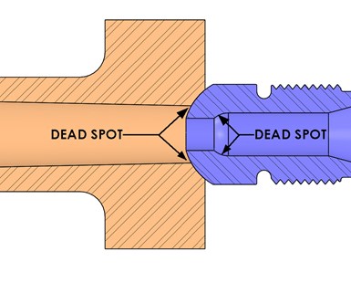
FIG 3 Dead spots on a general-purpose nozzle tip with a small orifice.
In addition to increased shear, a small nozzle-tip orifice will have a dead spot for material to stagnate, similar to the dead spot in a general-purpose nozzle tip, shown in Fig. 3. As the injected material rushes past this dead spot, it tries to pull the trapped or stagnant material out. Unfortunately, it also acts as a venturi and tries to pull air into the melt stream, which will look like splay on your parts. All of these reasons dictate why it is critical to properly size the machine nozzle-tip orifice to the sprue-bushing orifice.
It is critical to properly size the nozzle tip to the sprue bushing.
Plastic’s Technology Magazine’s Know-Column columnists (myself among them), are all highly experienced. We got that experience by making mistakes— lots of them. We take the time each month to share these mistakes with you, in the hope that you learn from them and don’t make them yourself.
About the Author
Jim Fattori
Jim Fattori is a third-generation injection molder with more than 40 years of molding experience. He is the founder of Injection Mold Consulting LLC, and is also a project engineer for a large, multi-plant molder in New Jersey. Contact jim@injectionmoldconsulting.com; injectionmoldconsulting.com.


Related Content

Cooling Geometry and the Reynolds Calculation
The original Turbulent Flow Rate Calculator worked well with a round circuit diameter, such as a drilled passage, but not as well using hydraulic diameters. Here’s how the problem was fixed.
Read More
Hot Runners: A View from the Bottom Up
Addressing hot-runner benefits, improvements, and everyday issues from the perspective of decades of experience with probably every brand on the market. Part 1 of 2.
Read More
Tunnel Gates for Mold Designers, Part 1
Of all the gate types, tunnel gates are the most misunderstood. Here’s what you need to know to choose the best design for your application.
Read More
Hot Runners: How to Maintain Heaters, Thermocouples, and Controls
I conclude this three-part examination of real-world problems and solutions involving hot runners by focusing on heaters, thermocouples, and controls. Part 3 of 3.
Read MoreRead Next

Lead the Conversation, Change the Conversation
Coverage of single-use plastics can be both misleading and demoralizing. Here are 10 tips for changing the perception of the plastics industry at your company and in your community.
Read More
How Polymer Melts in Single-Screw Extruders
Understanding how polymer melts in a single-screw extruder could help you optimize your screw design to eliminate defect-causing solid polymer fragments.
Read More
Why (and What) You Need to Dry
Other than polyolefins, almost every other polymer exhibits some level of polarity and therefore can absorb a certain amount of moisture from the atmosphere. Here’s a look at some of these materials, and what needs to be done to dry them.
Read More