Resin Conveying: No More ‘Spaghetti Bowl’
You now have technology choices to avoid the maze of conveying tubes that form a ‘spaghetti bowl’ or ‘rat’s nest’ in a central materials-handling system. Here’s how they stack up.
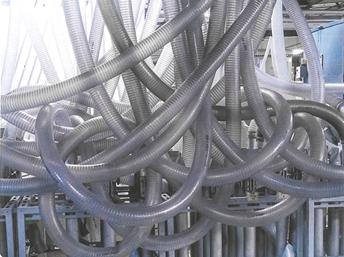
Large central materials-conveying systems can have 20 or more sections of flexible hose, each capable of being connected to 120 or more manifold sources. The end result is the “spaghetti bowl” effect that raises the risk that the wrong material will be sent to the machine.
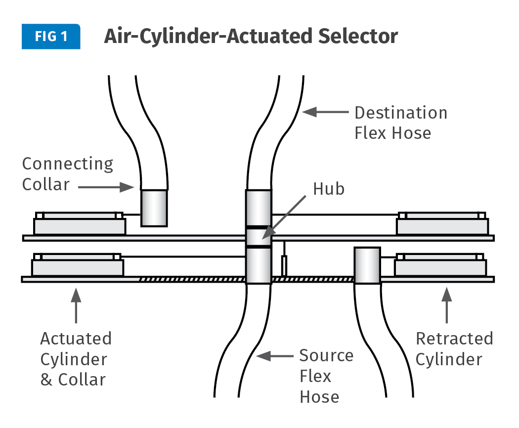
ACA selectors can handle up to 36 sources and destinations and operate with a single vacuum pump. Each source and destination on the ACA has a dedicated air cylinder with a flexible hose section and connecting collar that is aligned to a central hub
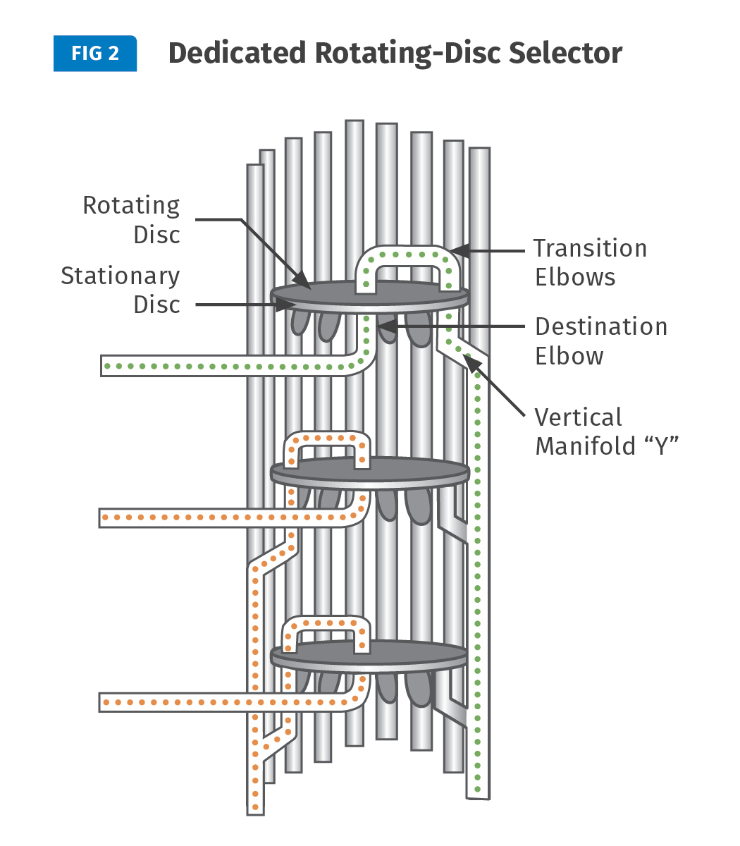
The RDS can have a maximum of 16 sources and 32 destinations. Each destination on the RDS has two discs: a top rotating disc with a single destination port, and a bottom stationary disc with an inlet port from each source. Each source has a vertical manifold with an exit “Y,” the branch of which is affixed to the stationary disc. To select material, the top disc is rotated and the destination port is aligned to a selected port on the stationary disc. Source: Motan Inc.
With Piovan’s RAS, material source/destination are mechanically changed after each filling cycle and locked into a machined seat.
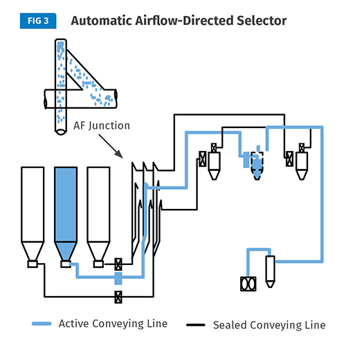
Patent-pending AutoFlow accomplishes material selection by directing the air, material, and flow from the source line through a source material valve and a traditional material manifold to an AF junction. The AF junction is a transition section that converts the source line to a destination line and directs the material into the destination line, where it passes through a destination material valve and on to the machine. Source: Vactec LLC


The introduction of central drying systems to the North American plastics processing market about 30 years ago drove suppliers of vacuum conveying systems to rethink their machine-loading philosophy. No longer was it a matter of simply conveying one material to a number of machines. Now 10, 20, or more materials had to be conveyed to an equal or greater number of machines.
The problem was further complicated by the fact that many of the materials were needed at multiple machines. The only way to solve this was to provide a dedicated manifold for every material, each with the appropriate number of “legs” to serve the machines that might require the specific material. If one material was required at eight destinations, the manifold would have eight legs, and if the next was required at four destinations it would have four legs, and so on.


As a result, a system with 20 materials and 20 machines could easily have 120 or more connection points on the manifold. Each machine would have a dedicated section of flexible hose, which had to reach and connect to every potential source position on the manifold and which might be 30-40-ft long. So you would have 20 sections of flexible hose, each capable of being connected to one of the 120 manifold sources: Behold, the birth of “spaghetti bowl.”
The multitude of connections and the spaghetti-bowl effect created a real risk of sending the wrong material to a machine, which was a sure recipe for disaster. Moreover, the physical challenges of just making the change meant that someone who understood how the system worked had to be on board at all times. Then the growing demands for molders to trace material and verify their process made it incumbent on suppliers to be able to prove what material was being processed at which machine. Getting the right material to the right machine became critical.
The flex hose itself was a problem: Abrasive materials would wear holes in the hoses over time and those leaks created a loss in capacity, not to mention increased possibility of pieces of grounding wire breaking off and getting into the mold. All in all, there was plenty to go wrong.
Most U.S. suppliers of conveying systems have taken the path of offering a “proofing” solution to validate source and destination connections. In most cases, the proofing is accomplished by using the electrical connection between the embedded grounding wire in the destination flex hose and the source manifold.
For example, Wittmann Battenfeld, Torrington, Conn., has developed an RF connection that verifies the appropriate source and destination without the problems of grounding-wire connections. Novatec, Baltimore, uses an angular, upright, closed-cabinet design with a “hidden wire” principle, as well as self-sealing manifold connectors. In both, an operator can preselect sources and destinations at the control panel and then match the physical connections. Once the correct selection is made the system can run; if incorrect, the system alarms.
Both of these methods solved the source/destination problems, but you still had the flex-hose “bowl” to deal with. The operator still had to muscle his way through the spaghetti maze and fight holes in hoses, broken wire contacts, wire contamination, and other issues.
A number of European suppliers saw that these issues went beyond the manual connection and proofing systems and developed fully automatic systems. The earliest of these Automatic Coupling Stations, as they were called, was installed in the late 1980s in Switzerland at a completely “lights out” facility that was years ahead of its time.
These developments continued to grow and now most all of the major European system manufacturers offer some type of automated material-selection system. Currently, there are three basic types offered, plus one brand-new one:
1. Air-cylinder-actuated selectors, like the Navigator from Germany’s Koch Technik, and the Dolphin from Moretto of Italy, represented here by Advanced Blending Systems, Menominee, Mich. These use air cylinders to change source and destination after each fill cycle.
2. The rotating-arm style selector, from Italy’s Piovan (supported in North America by subsidiary Universal Dynamics, Woodbridge, Va.). With this technology, source and destination are mechanically changed after each filling cycle.
3. The dedicated rotating-disc selector from Motan Inc., Plainwell, Mich. Called MetroLink, this system changes position when a material change at the machine is called for.
4. The new airflow-directed selector from Vactec LLC, Kalamazoo, Mich. Dubbed the AutoFlow, this system changes source to destination by managing air flow.
Following is a brief overview of how the various systems work. The cost factor mentioned is assuming a proofing manifold and controls for 20 sources to 20 destinations as the base offering (“X”).
AIR-CYLINDER-ACTUATED SELECTORS (ACA): ACA selectors can handle up to 36 sources and destinations and operate with a single vacuum pump. Each source and destination on the ACA has a dedicated air cylinder with a flexible hose section and connecting collar that is aligned to a central hub (Fig. 1). When material is required at a specific destination, the preprogrammed source and destination cylinders are actuated, and they meet at the hub. Once the connection is confirmed, the conveying cycle commences.
Upon completion of the cycle, the cylinders return to their “at-rest” position and the next cycle with a new source and destination is activated.
This selector is normally mounted vertically and requires a reasonably small footprint but a fair amount of headroom. The entry flow through this type of selector is fairly smooth and the pressure drop is minimal and is equivalent to two to three elbows.
Other factors to consider with this technology include:
• Flexible hose sections are required for each source and destination.
• Any maintenance or service shuts down the entire conveying system.
• The unit must be enclosed by a safety cage.
• Confirmation of alignment and an air-tight seal at the hub are critical.
• The ACA does not operate with multiple vacuum systems; there is one selector per pump.
• Pressure drop through the ACA is equal to 2-3 elbows.
• Controls require a special interface for suppliers other than the original manufacturer.
• All material flows through a common hub.
• Cost factor is 2–3 X.
ROTATING-ARM SELECTORS (RAS): These can have up to 60 inlets and outlets and operate with a single vacuum pump. The RAS units have rigid pipe connections for each source entering the vertical assembly and departing it for each destination. Both the sources and destinations have a dedicated rotating arm that rotates with and aligns itself with the pre-chosen source and destination port. The RAS has no flexible hoses. Connections to the preselected positions are made by means of a positioning drive, encoder, and locking air cylinder for both destination and source.
The drive aligns the arm to the position, confirms with the encoder, and locks in place with the air cylinder, providing final confirmation. Once the source and destination have been confirmed, the conveying cycle can start, with all material flowing through the two arms joined by a connecting coupling. Upon completion of the cycle, the source and destination arms are repositioned to new sources and destinations, and the cycle is repeated.
Other factors to consider with this technology include:
• Internal pipes can be ceramic coated for abrasion.
• Rotation can be in either direction.
• All material must flow through the rotating arms.
• Maintenance or service shuts down the entire conveying system.
• It is completely enclosed.
• Controls require a special interface for suppliers other than OEM.
• It does not operate with multiple systems; one connector per pump.
• It has a small footprint but requires a fair amount of height.
• Pressure drop for airflow through the RAS is equivalent to two elbows
• Cost factor = 2–3 X.
ROTATING-DISC SELECTOR (RDS): The RDS can have a maximum of 16 sources and 32 destinations (Fig. 2). Each destination on the RDS has two discs: a top rotating disc with a single destination port, and a bottom stationary disc with an inlet port from each source. Each source has a vertical manifold with an exit “Y,” the branch of which is affixed to the stationary disc. To select material, the top disc is rotated and the destination port is aligned with a selected port on the stationary disc.
When the conveying cycle begins, the material passes through the “Y,” the discs, and two short-radius transition elbows that are affixed to the rotating disc. The material continues its path through the transition elbows to the center of the two discs, where the flow connects to a third short-radius elbow is at the hub of the stationary disc, from which it flows through a conveying line to the machine.
As each disc is dedicated to a machine, the material-change process only occurs when a new material is required at the machine. When this occurs, the disc rotates to a new “Y” section on a different manifold, and the destination has a new material.
Other factors to consider with this technology include:
• No flexible hoses.
• A disc is repositioned only for material change.
• Material only flows through the selected disc.
• High pressure drop: Three short-radius elbows equal six elbows.
• Small footprint, fairly compact.
• Maintenance and service can be performed without interrupting system operation.
• Proprietary controls make interface with non-OEM
system difficult.
• Cost factor = 3-4 X.
AUTOMATIC AIRFLOW-DIRECTED SELECTOR (AutoFlow): The patent-pending AutoFlow accomplishes material selection by directing the air, material, and flow from the source line through a source material valve (SMV), and a traditional material manifold to an AF junction. The AF junction is a transition section that converts the source line to a destination line and directs the material into the destination line, where it passes through a destination material valve (DMV) and on to the machine (Fig. 3).
All source lines have an SMV valve and all destination lines DMV valves. The chosen source and destination valves are open. As all others are closed and the air flow is isolated, the air and material can only take the path from the source through the open valves and Junction to the vacuum receiver.
The DMV valves are activated by the sequence valve on the vacuum hopper and the source valve is controlled by the purge valve at the source. This allows interfacing with virtually all existing control platforms.
The AF junction transitions flow from the selected source line to the selected destination line. The AF junction’s proprietary, abrasion-resistant, angled vertical inlet assures straight-through flow to the terminal point in the system.
Other factors to consider with this technology include:
• Saves space by eliminating the need for a central manifold area.
• No flexible hose.
• No valves at material junctions.
• Interfaces with any control package.
• Abrasion resistant.
• Low pressure drop; the junction is equivalent to two elbows.
• Open, easy access to all valves and junctions.
• Can be retrofitted to existing systems and controls
• Cost factor 1.5–2 X.
• Maintenance can be performed on valves and junctions without interrupting system operation.
So, can you afford to automate your material selection manifold? Or maybe—when you consider costs of validation, contamination, uptime/downtime, maintenance, the flexible-hose “spaghetti bowl,” or the possibility of a “lights out” operation—the better question to ask yourself is: Can you afford not to?
Related Content

How to Get Rid of Bubbles in Injection Molding
First find out if they are the result of trapped gas or a vacuum void. Then follow these steps to get rid of them.
Read More
How to Optimize Pack & Hold Times for Hot-Runner & Valve-Gated Molds
Applying a scientific method to what is typically a trial-and-error process. Part 2 of 2.
Read More
How to Set Barrel Zone Temps in Injection Molding
Start by picking a target melt temperature, and double-check data sheets for the resin supplier’s recommendations. Now for the rest...
Read More
Solve Four Common Problems in PET Stretch-Blow Molding
Here’s a quick guide to fixing four nettlesome problems in processing PET bottles.
Read MoreRead Next

Processor Turns to AI to Help Keep Machines Humming
At captive processor McConkey, a new generation of artificial intelligence models, highlighted by ChatGPT, is helping it wade through the shortage of skilled labor and keep its production lines churning out good parts.
Read More
Advanced Recycling: Beyond Pyrolysis
Consumer-product brand owners increasingly see advanced chemical recycling as a necessary complement to mechanical recycling if they are to meet ambitious goals for a circular economy in the next decade. Dozens of technology providers are developing new technologies to overcome the limitations of existing pyrolysis methods and to commercialize various alternative approaches to chemical recycling of plastics.
Read More
Why (and What) You Need to Dry
Other than polyolefins, almost every other polymer exhibits some level of polarity and therefore can absorb a certain amount of moisture from the atmosphere. Here’s a look at some of these materials, and what needs to be done to dry them.
Read More