The Right Way to Design Vents in Single-Screw Extruders
Designing vents for single-screw extruders requires understanding of polymer flow in the screw channels. Some designs are more effective than others. Here are some guidelines.
.jpg;width=70;height=70;mode=crop;format=webp)


To actually design a vented screw for a single-screw extruder you must first understand how extruder vents actually work. Take a look at Fig. 1. The first metering section is typically completely filled with polymer (A), and as it goes into the vent section (B) the channel volume is increased to eliminate any pressure in that area and develop an open space.
The open space forms on the downstream portion of the screw channel because the angled screw flight is pushing the contained polymer. A vent insert or “deflector” is required in the barrel opening to prevent any vent flow that would plug the hole to atmosphere or vacuum. Deflector design is critical — without it no screw design will vent properly.


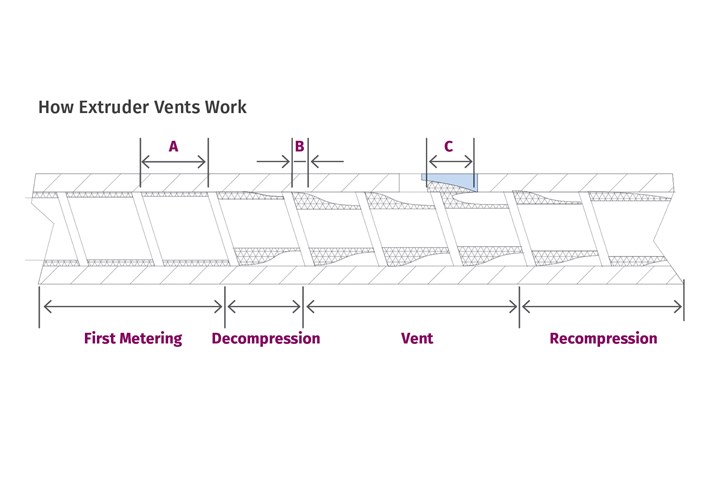
FIG 1 As shown here, the first metering section is typically completely filled with polymer (A). As it goes into the vent section (B), the channel volume is increased to eliminate any pressure in that area and to develop an open space for volatiles to collect.
The deflector is configured so that the amount of polymer that “squishes” out as the screw flight passes the vent opening (C) will be scraped off and accumulate in the relief area. The amount must be small enough to only partially fill the relief area without pushing any polymer back into the vent hole. The amount caught in the relief area is pushed out by the next flight and simply refilled. If the relief is properly sized to the amount being scraped off, the vent to atmosphere stays open and it becomes a steady-state process allowing volatiles to exit.
Proper vent design requires understanding of polymer flow in the screw channels and is not just a simple ratio to the first metering depth. I always find these screw design principles easier to understand if the observation point is changed so that the barrel is rotating around a stationary screw. It’s like being on a “merry go round” and watching the landscape go by. Whether you are on or off the “merry go round” has no effect on the results.
The melted polymer is always stuck to both the screw and barrel, and if we assume the different observation point of a stationary screw, the motion of the polymer in the channel is equal to the rotating barrel speed at the barrel wall and zero at the screw root (Fig. 2). Across the channel depth, the polymer is transported forward by the combination of the rotating shear stress and the angle of the screw flight.
The exact 3D shape of the shear-stress curve and resultant velocity (V) is complex and largely dependent on the polymer viscosity. For a partially filled channel in the vent area (B in Fig. 1), the lower the viscosity the more the polymer “sags,” causing the barrel contact area to become narrower. Additionally, the shear-stress level deteriorates more quickly as it approaches the screw root. That has a negative effect on the flow rate in the vent.
So proper vent design requires a knowledge of the viscosity at the shear rate and melt temperature of the polymer in the vent. The forward transport or output is then a combination of the angle on the flight or scraper and the viscosity and the amount of polymer in contact with the barrel wall (B). This is unlike the full channel, where the entire channel width contributes to forwarding.
Proper vent design requires a knowledge of the viscosity at the shear rate and melt temperature of the polymer in the vent.
As the channel deepens entering the decompression section, the amount of polymer in contact with the barrel wall decreases. That decrease has to be made up with the increased volume in the channel. But it’s not simply a fixed ratio but a combination of several screw-design features and the viscosity of the polymer in that moving bank.
Channel depth can have surprisingly little to do with the amount of forwarding since it’s always controlled by the width of the polymer in contact with the barrel wall (and is zero at the screw root), as well as the viscosity. If there is vent flow, one typical reactions is to deepen the channels in the vent, which often has little effect.
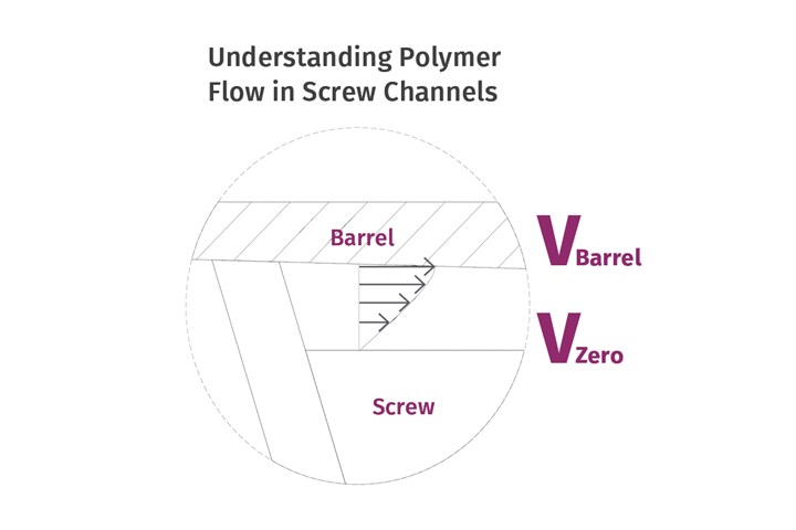
FIG 2 The exact 3D shape of the shear-stress curve and resultant velocity (V) is complex and largely dependent on the polymer viscosity. From the point of view of a stationary screw and rotating barrel, the motion of the polymer in the channel is equal to the rotating barrel speed at the barrel wall and zero at the screw root.
I’ve seen see very few rigorously designed decompression sections, as it’s common in screw design to simply use a ratio to the first metering depth to design the vent. Its typically between 2:1 and 3:1 of the first metering depth. However, proper design should also be based on a series of calculations instead of just a simple ratio. When designing for new polymers — or those modified with fillers, containing significant volatiles and various additives — that approach does not always work. For example, vent design is particularly important for high-melt-flow polymers because the shear stress deteriorates more quickly towards the screw root, reducing the mass flow.
With the intention of improving devolatilization with more renewal of the surface area, I see some many designs with multiple flights. These designs feature an increase in the flight pitch in the vent, based on the idea that this technique will allow more space to develop the open area needed for proper devolatilization.
Vent design is important for high-melt-flow polymers because the shear stress deteriorates more quickly towards the screw root, reducing the mass flow.
Longer pitch is not a terrible idea, as it improves surface exposure, but considerable care must be exercised with that approach. Multiple flights take up more space, not allowing enough separation between the bank and barrel wall (B) to permit good venting. To compensate, these designs often use deeper channels or longer flight pitch to allow for more open space in the vent. Longer pitch makes it extremely sensitive to even the slightest head pressure. Even a few hundred psi will flood most vents, so additional considerations must be made to prevent any pressure at the discharge of the vent if using a longer pitch. And even at open discharge, the re-compression of the melt going up the second taper can create enough backpressure to flood the vent.
Recently, I examined a screw with venting problems and calculated for a 0.3 MI HDPE that it would take only several hundred psi to flood the entire vent on that particular screw. Also, when using multiple flights, you need to incorporate special features at the inlet to the vent that will allow all the channels to fill evenly or you will have intermittent vent flow.
Good venting!
ABOUT THE AUTHOR: Jim Frankland is a mechanical engineer who has been involved in all types of extrusion processing for more than 50 years. He is now president of Frankland Plastics Consulting LLC. Contact jim.frankland@comcast.net or (724)651-9196.
Related Content

Understanding Melting in Single-Screw Extruders
You can better visualize the melting process by “flipping” the observation point so that the barrel appears to be turning clockwise around a stationary screw.
Read More
How Polymer Melts in Single-Screw Extruders
Understanding how polymer melts in a single-screw extruder could help you optimize your screw design to eliminate defect-causing solid polymer fragments.
Read More
Formulating LLDPE/LDPE Blends For Abuse–Resistant Blown Film
A new study shows how the type and amount of LDPE in blends with LLDPE affect the processing and strength/toughness properties of blown film. Data are shown for both LDPE-rich and LLDPE-rich blends.
Read More
Cooling the Feed Throat and Screw: How Much Water Do You Need?
It’s one of the biggest quandaries in extrusion, as there is little or nothing published to give operators some guidance. So let’s try to shed some light on this trial-and-error process.
Read MoreRead Next

Understanding Melting in Single-Screw Extruders
You can better visualize the melting process by “flipping” the observation point so that the barrel appears to be turning clockwise around a stationary screw.
Read More
Processor Turns to AI to Help Keep Machines Humming
At captive processor McConkey, a new generation of artificial intelligence models, highlighted by ChatGPT, is helping it wade through the shortage of skilled labor and keep its production lines churning out good parts.
Read More