
Melt Delivery Systems: Going Against Tradition
When it comes to part design, the importance of a properly designed melt delivery system is often neglected.


When it comes to part design, the importance of a properly designed melt delivery system is often neglected.
A well designed part is only as good as the melt delivery system feeding it. The goal of a properly designed melt delivery system is to create uniform melt conditions to each gate while accommodating filling pressure limitations, minimizing shear, and providing for cavity packing.
Traditionally, melt delivery systems are sized based on estimates, similar part geometry, or poor design guidelines. However, when sizing a runner, it is important to minimize any restrictions of the material flowing through the channel. The cross-sectional area (diameter) of the melt delivery system has the biggest impact on both pressure drop and shear rate through the channel. At a constant flow rate, both pressure and shear rate will increase with decreasing runner diameter to a point.


The pressure on plastic melt can be quite high during both mold filling and packing phases. During mold filling, the pressures can exceed 20,000 psi, with a maximum pressure at the injection nozzle and zero pressure at the flow front. Under high pressures, plastics are compressible, and that compression increases the interaction of the polymer chains, resulting in an increase in the resistance to flow or increase in viscosity. This phenomenon usually occurs at the gate when the formerly free flowing material suddenly hits a restrictive geometry. As a result, back pressure develops which in turn spikes the velocity of the material through the gates causing excessive shear rates.
During the injection molding process, excessive shear rates can typically lead to both shear-induced stress and degradation. Shear-induced stress results from the resistance to flow as the polymer chains drag, or stretch, against the cavity wall in the direction of flow. As a result, these residual stresses can contribute to distortion or premature part failure. If the shear rate becomes too excessive, the polymer chains can degrade as a result of being physically torn apart,which can affect both physical and cosmetic properties of the molded part.
To avoid excessive pressure limitations and shear rates, modifications to the melt delivery system need to be made to avoid restrictions in the melt stream. Starting at the sprue, it is recommended that its rear opening should be 1.5 mm larger than the nominal wall thickness of the part being molded. However, depending on the flow length and part volume, this opening may need to be widened further (2-3 times the nominal wall) to compensate for the added volume.
Sizing the Primary Runner
As a rule of thumb, the diameter of the primary runner, or enclosed diameter in a trapezoidal runner, should match the diameter of the rear opening of the sprue to maintain a constant volumetric rate of filling. The cross-sectional area of the following runner branches (secondary, tertiary, etc.) should be stepped down roughly 15% respectively to maintain an unrestrictive volume of material at a constant flow rate. Fishbone and non-geometrically balanced runner layouts should be avoided because they cannot provide uniform conditions to the multiple gates they are feeding. In a multi-cavity runner layout or a single cavity tool with multiple gates, in most cases, the flow length between the sprue and each gate should be identical to provide the most uniform melt conditions through each gate, depending on the part geometry.
The gate is the critical connection between the runner system and the part geometry that can significantly affect the ability to successfully mold a part. Too small of a gate causes a disturbance in the melt, which restricts the natural flow of the material. As previously stated, this can cause excessive shearing of the material or other gate-related defects. To avoid such issues, against standard traditions and practices, gates should be sized 75-100% of the wall thickness of the part to which it is attached. By doing so, the restriction of the free flowing material through the runner channel will be minimized. In addition to the size of the gate, the transition between the feeding branch and the gate must be properly tapered and given generous radii. Sudden sharp edges act like a knife-edge which can shear the material as well.
Should You Add Cold Slug Wells?
Another factor to consider while designing an optimum runner system is to add cold slug wells.
Cold slug wells are used in cold runner systems to capture cold slugs. Cold slugs are solid, or partially solid, pieces of plastic that form in the nozzle tip as a result of its contact with the cold mold. During injection, the cold slug is injected into the sprue and travels through the melt stream. If the cold slug is not captured, it may disrupt the flow by partially or completely blocking the melt stream. By extending the runner branch feeding into an intersection, this provides a place for the cold slug to be captured before it reaches the part cavity. It is common practice to have a cold slug well at the base of the sprue and at each intersection in the runner system. The cold slug well should maintain the same diameter as the runner branch feeding into the intersection and extend 1.5 – 2.0 times the diameter past the intersection.
Larger Gates, Less Shear, Few Cosmetic Defects
The melt delivery system is the critical channel connecting the molding machine with the part geometry. As against common practice, the benefits of a larger gate minimize the effect of shear induced stresses and cosmetic defects associated with undersized gates and as a result, a wide, robust processing window is achieved.
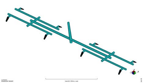
As an added note, as with all designed melt delivery systems, a mold simulation analysis should be completed to ensure the design is within recommended processing limits. While setting up the analysis, beam elements should be used to simulate the runner system while triangular elements (Dual-Domain) or tetrahedral elements (3D) can be used to finely mesh the gates. Simply using injection cones attached to the part geometry is not an accurate representation of the injection molding process and will result in misleading outcomes. Figure 1 (below) represents a melt delivery system (part geometry hidden) composed of beam elements and triangular elements modeled in to accurately perform a mold filling simulation utilizing Autodesk Moldflow.
About the author
Stephen Levy graduated from Penn State Behrend in December, 2015 with a degree in Plastics Engineering Technology. He currently works as an ADTS Engineer at PolyOne in Avon Lake, OH where he provides CAD design and Moldflow simulation support. Stephen is also a content contributor for Elite Machinery Systems.


Related Content

50 Years of Headlines … Almost
I was lucky to get an early look at many of the past half-century’s exciting developments in plastics. Here’s a selection.
Read More
Take Time to Save Time: Five Steps in Mold Design to Reduce Back-End Troubleshooting
Westminster Tool shares how the one week it typically takes to perform these five steps in the design phase can save three weeks or more in an overall tool build.
Read More
50 Years...600 Issues...and Still Counting
Matt Naitove marks his first half-century in plastics reporting, with a few of his favorite headlines.
Read More
Injection Molding Simulation Meets the Real World
Direct data interface between molding simulation and the injection machine links the computer model to the real-world process. This can improve results from product and mold design through ongoing production. A case study demonstrates these benefits for automotive components in a family mold.
Read MoreRead Next

For PLASTICS' CEO Seaholm, NPE to Shine Light on Sustainability Successes
With advocacy, communication and sustainability as three main pillars, Seaholm leads a trade association to NPE that ‘is more active today than we have ever been.’
Read More
Beyond Prototypes: 8 Ways the Plastics Industry Is Using 3D Printing
Plastics processors are finding applications for 3D printing around the plant and across the supply chain. Here are 8 examples to look for at NPE2024.
Read More
People 4.0 – How to Get Buy-In from Your Staff for Industry 4.0 Systems
Implementing a production monitoring system as the foundation of a ‘smart factory’ is about integrating people with new technology as much as it is about integrating machines and computers. Here are tips from a company that has gone through the process.
Read More