


In blown film, bubble management is essential to achieve consistent film quality, physical properties and successful winding. When diagnosing winding or quality defects, the bubble “speaks.”
Reflect on a time when your blown-film line was new or newly upgraded, or had just gone through a complete preventive-maintenance program. The line is clean, calibrated and aligned. It starts up, and the process team has it tuned and running the best product ever. The bubble is perfect. It is a “happy bubble,” locked into the air ring and with the frost line at the perfect height; level, straight, no dips, no spikes and no bubble flares. Perfect. Burn that image into your mind. From that image, the discerning eye will easily spot an “unhappy bubble” from across the factory to diagnose quality defects.


Defect Identification & Tracking
The intent of this article is not to enumerate every defect and every known cause. It is to demonstrate how mapping can be used to properly define a defect and narrow down, as quickly as possible, the list of suspects causing the issue.
When addressing blown-film quality defects, issues will always relate to man (process, procedure), machine (design, maintenance), or material (spec change, contamination). Mapping is a powerful troubleshooting approach for identifying the culprit, but requires patience to gather data methodically, plot and map the data, interpret the shape of the map, and find the interacting conditions. The goal is to narrow down possible contributors.
• Does the defect vary with time? If so, what is the cycle time?
• Is the position stationary or moveable? Can I force it to move?
• Can the shape of the defect be matched to anything in the process?
• Is there more than one cause of the defect?
Plastics behavior is governed by temperature, stress∕strain and time. Determining the cause-and-effect relationships of a particular defect warrants creative approaches and thinking. Mapping an image of the defect and finding the switches that interact with its shape or position can lead to devising a solution.
When acting as a troubleshooter there are a few clichés that provoke creative thinking:
1. Reality often astonishes theory.
2. Empirical data rarely lies, you just need to learn how to read it.
Most of the time, film rolls are simply a raw material used in a subsequent conversion process to turn the film into a value-added product. Some conversion processes are very sensitive to the straightness and flatness of the plastic web (Fig. 1). A poorly wound film roll can adversely affect converting speed and cause process or product defects, increasing scrap. Most times, a poorly wound roll is related to excessive gauge variation of some type.
Mapping can help magnify small variations into a useable picture. Mapping can also show no correlation, ruling a factor out rather than in.
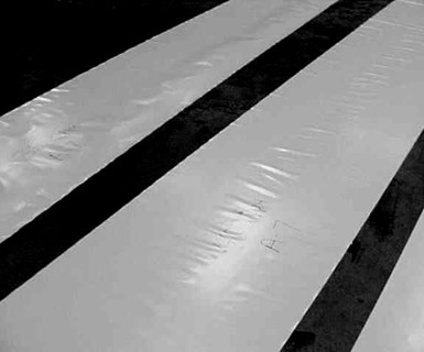
FIG 1 Baggy film during unwind.
Here are some considerations to investigate:
• Is there a pattern to the defect? Does it have a frequency? Does the frequency match any known flow or temperature pattern? How many die ports? How many air-ring ports?
• Is it a discrete defect? An anomaly related to a contaminant buildup or hardware failure?
• Where is the first place it appears in the process? This will tell you where to start mapping.
• Is the variation in the machine direction or transverse direction? Total gauge variation is comprised of both. They must be separated to determine each one’s degree of influence.
Following are three case studies that illustrate how mapping can be used to find the root cause of blown-film issues. Each uses the same mapping technique in a different manner, showing its versatility.
Case Study One
Defect: Collapsing wrinkles vary with the oscillating hauloff rotational position, i.e. bubble position.
Symptom: Tilted frost line, frequency of 1 (Fig. 2). Anything that disrupts the cooling uniformity in that same shape is a possibility: volume, temperature or alignment.
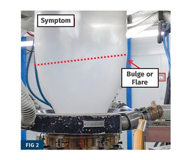
FIG 2 Here, a tilted frost line resulted in collapsing wrinkles with the oscillating hauloff or bubble position. The thickness profile appeared to match the shape of the defect.
Parameters mapped (positional variation):
• Thickness profile: Appears to match the shape of the defect.
• Die gap: Measured and within tolerance.
• Temperature variations:
1. In the melt stream, cross-direction and machine-direction: measured and within tolerance.
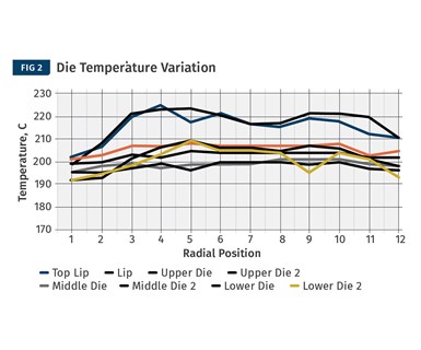
2. Surface temperature around the die appears to match the shape of the defect. What makes the mapping a challenge here is the effect of spiral flow inside the die. Since some of the temperature variation is below the spirals, the thermal variation in the die or melt will shift with the flow around the spiral. The defect, as seen in the bubble shape, will not always align with the position of the initial cause. In this three-layer die, two spirals flow counterclockwise and one flows clockwise, further affecting the mapping.
This is why creative thinking and multiple maps are required.
Resolution: A poorly placed thermocouple, together with a watt-density imbalance at lowest die zones caused uneven heating.
As it happens, the surface temperature around the die appears to match the shape of the defect.
Case Study Two
Defect: Baggy film during unwind (Fig. 1).
Symptom: Humps on wound rolls correlating to baggy lanes at unwind; frequency of 5-6 (Fig 3).
Parameters mapped (positional variation):
• Wound roll weights: When running multiple lanes of product, this method essentially identifies broad-width, non-measurable, non-oscillating (standing) gauge variations through magnification. Variation in roll weights or case weights (bags) within a “set” indicates variable average thickness around the bubble.
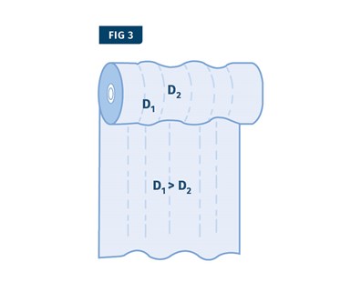
FIG 3 Humps on the wound rolls correlating to baggy lanes at unwind. Source: Equistar.
• Wound roll diameter: This measurement is similar to the above, but can measure narrower-width gauge variation. In a 30-in.-diam. roll of 0.002-in.-thick film, there are over 6500 wraps, or individual layers of film. If a non-randomized variation of only 1% accumulates on the roll, there will be a 5∕16-in. diametric difference at 30-in. finished diameter. Where there is a positive diameter difference, the film will stretch and cause bagginess at the unwind.
The severity of this problem depends on the extensibility of the film and the forgiveness of the downstream converting operation.
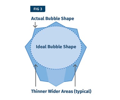
FIG 3 Thin and thick areas of the non-ideal bubble result in diameter differences on the wound roll.
Data was generated to determine any correlation of the winding defect to an air ring (after cleaning) and a subsequent change of the air-ring position on the die (Fig. 4).
Resolution: In this case, the process used a six-port air-ring body that most closely matched the shape of the defect. Mechanical and wear issues with the air ring (end of useful life) were determined to be a strong influence. A new air ring reduced the defect to an acceptable level.
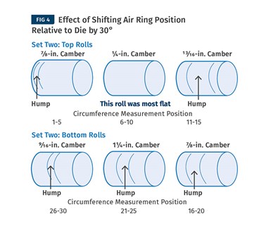
FIG 4 Five circumference readings on each roll were polar plotted (see below). The data was generated to determine any correlation of winding defect to the air ring vs. die.
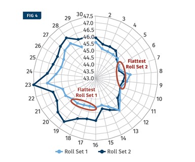
FIG 4 This polar view relates the wound roll defect to the bubble shape.
Case Study Three
To fully understand the root cause of complex defects, it is necessary to consider the role of time as a variable.
Defect: Baggy film during unwind.
Symptom: The gauge band in the wound roll causes a baggy lane in the unwound film. The gauge band occurs anywhere across the roll sets, yet it does not move across the web when the film is unwound. The process uses oscillating nip and back-to-back winders. The gauge range is typically within ±10%. Winder shafts have been changed and core thickness increased, but no improvement resulted.
Parameters mapped (positional variation): The customer used the mapping technique to rule out all the usual suspects. What was left was a defect that varied randomly with both position and time.
Resolution: There is a stationary gauge effect that occurs randomly across the wound roll sets, revealing that the oscillation speed of the hauloff was suspect. The film build-up is greatest near the core. If the film is not randomized quickly enough, a thick spot on the bubble (Fig. 5) accumulates as a high gauge band at the film core.
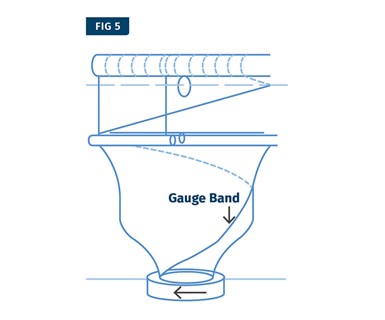
Gauge band will be at a random start position on core, depending on index cycle time.
Since the film core is the foundation for the rest of the wound roll, the high gauge band stretches the film building upon it, causing the baggy lane (Fig. 6). The thick spot on the bubble is being randomized (albeit slowly) by the oscillating hauloff. But a gauge band is created at the core, the position of which is a function of where the bubble’s thick spot lands at cutover. To correct the issue, slowly increase the oscillation speed until the problem goes away.
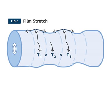
FIG 6 Roll diameter variations caused by film stretching.
These are just a few examples of how mapping can be used as a troubleshooting technique. To fully understand the root cause of complex defects, it is necessary to create as many maps as possible. The more parameters mapped, the more likely a useful interaction will be found.
About the Author: Bill Hellmuth is product manager for blown film at for Davis-Standard. With more than 30 years of technical sales and marketing support for Gloucester Engineering’s (Now Davis-Standard’s) global product line of blown film machinery, his responsibilities have included film extrusion machinery sales, technical customer support, and product development. Contact 978-282-9290; whellmuth@davis-standard.com; davis-standard.com.


Related Content

Formulating LLDPE/LDPE Blends For Abuse–Resistant Blown Film
A new study shows how the type and amount of LDPE in blends with LLDPE affect the processing and strength/toughness properties of blown film. Data are shown for both LDPE-rich and LLDPE-rich blends.
Read More
Film Processor Automates Complex Resin Management, Blending & Distribution System
Polipak of Poland moves to BlendSave system to support sustainability and Industry 4.0 objectives.
Read More
Filtration System Helps Film Processor Manage Recycled Material Mandates
Global film processor RKW teams with Nordson to enable it to process blown film with high recycled content.
Read More
Roll Cooling: Understand the Three Heat-Transfer Processes
Designing cooling rolls is complex, tedious and requires a lot of inputs. Getting it wrong may have a dramatic impact on productivity.
Read MoreRead Next

Lead the Conversation, Change the Conversation
Coverage of single-use plastics can be both misleading and demoralizing. Here are 10 tips for changing the perception of the plastics industry at your company and in your community.
Read More
People 4.0 – How to Get Buy-In from Your Staff for Industry 4.0 Systems
Implementing a production monitoring system as the foundation of a ‘smart factory’ is about integrating people with new technology as much as it is about integrating machines and computers. Here are tips from a company that has gone through the process.
Read More
Recycling Partners Collaborate to Eliminate Production Scrap Waste at NPE2024
A collaboration between show organizer PLASTICS, recycler CPR and size reduction experts WEIMA and Conair will seek to recover and recycle 100% of the parts produced at the show.
Read More