Roll Cooling: Understand the Three Heat-Transfer Processes
Designing cooling rolls is complex, tedious and requires a lot of inputs. Getting it wrong may have a dramatic impact on productivity.
.jpg;width=70;height=70;mode=crop;format=webp)


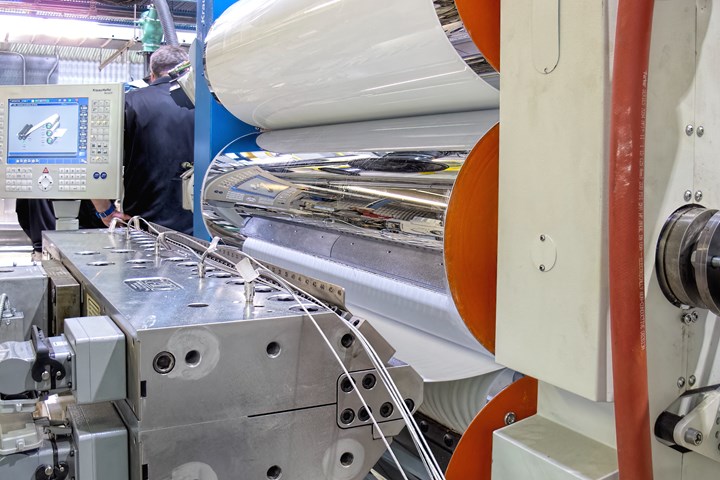
Roll cooling depends on water flow rate and temperature and the heat-transfer efficiency of the roll materials and the plastic itself. (Photo: Matthew Naitove)
Cast film, sheet, coatings, etc. are all produced using chill rolls. Yet the science behind roll cooling is very limited at the processor level, and even among some roll manufacturers I contacted. Many roll manufacturers simply fabricate a roll based on its outside dimensions with little regard for the three different heat-transfer processes involved.
Roll cooling combines three different heat-transfer processes. First is water cooling, to remove heat from the roll itself.
Recently I was contacted by a processor that was going to make some thick sheet — from 1 to 1.25 in. — and was going to simply use a ratio of the output in pounds per hour to scale up the roll circumference of the new sheet stack from another totally dissimilar sheet cooling application. The processor’s first assumption that roll cooling capacity was proportional to roll circumference was erroneous for a new sheet line, and my own calculations found the line’s capacity would have been less than half the desired level.


Three Different Heat-Transfer Processes
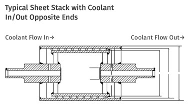
Roll cooling is a combination of three very different heat-transfer processes. First is the water cooling. There must be enough coolant flow at a specific temperature to remove the heat from the roll itself. The limits on water cooling are dependent on coolant flow rate and its resultant velocity at the inside surface of the outer shell, as well as its temperature differential relative to the shell. The coolant must flow through the roll at a minimal velocity to create turbulence at the inner wall of the outer shell, or the cooling rate drops drastically. That requires pressure-drop calculations through the entire roll and cooling system, as well as calculating the actual pump capacity at that head pressure.
The second heat-transfer process is the transfer of the heat through the outer shell. Since it is typically made of steel with chrome plating, the outer shell has a relatively high transfer rate and generally is not the limiting factor on most roll designs. However, it must be calculated and combined with the other two heat- transfer processes to perform the complete analysis.
In a typical three-roll stack you are using about half the surface areas of the middle and bottom roll and a very small portion of the top roll, since the polymer contact area is only a few inches of the circumference for the top roll. The top roll primarily sets the gauge and is not a large part of the cooling process, so it can be smaller and require less coolant. However, roll deflection must also be considered for the top roll, so its size is not really arbitrary.
On thin sheet, the coolant is often the limiting factor on output.
The third heat-transfer process involves the thermal conductivity of the polymer, its thickness and its heat content. Its heat content is its melt temperature minus the desired exit temperature, times the output and specific heat. Everything must be sized for these three factors as the heat- transfer rate of the entire cooling process is like a composite of three different layers. The entire cooling process looks a lot like a composite layer.
Delta T=[t1÷K1A + t2 ÷ K2A + t3÷ K3A] Q
The change in temperature is inversely proportional to the thickness of each layer and proportional to the thermal conductivity of each layer and its contact area.
The plastic itself can be the limit on the whole process based on its thickness. On thin sheet, the coolant is often the limiting factor on output. Doubling the thickness at the same output requires essentially twice the time on the rolls to remove the desired heat because of the controlling heat-transfer rate of the polymer. Consequently, the output and thickness have to be considered to size the rolls, assuming the same width. Thermal conductivity of the three mediums, for example, are:
Mild steel: 0.45 W/mK-1
Water: 0.60 W/mK-1
LLDPE: 0.33 W/mK-1
Air: 0.028 W/mK-1
In a three-roll stack, the sheet contact with the rolls switches sides as it passes from the middle roll to the bottom roll, somewhat reducing the heat-transfer time from the sheet. That alone is a very complex calculation but can be approximated . As you can see, the polymer almost always has the lowest heat- transfer rate, which can make it the controlling factor in the cooling capacity of a roll stack. Air cooling with roller tables as a replacement for proper roll design is a poor substitute and adds to the length of the line and its cost.
Additionally, each polymer’s specific heat and melt temperature form the heat load on the roll stack, along with the output. Since different polymers’ specific heat, melt temperature, and density vary considerably, the heat transfer of these polymers will vary and lead to major changes in cooling capacity for a specific roll stack.
Be sure you understand how your rolls are being designed, or whether they are even being designed, if you are counting on the result.
The proper design of cooling rolls is actually quite complex and somewhat tedious, as there are a lot of calculations involved. Yet I just got a quotation for a sheet cooling roll and the manufacturer did not ask for the output, sheet thickness, polymer type, coolant capacity, nip loading, or input/output temperatures. Once you add roll deflection to the thermal design, it gets even more complicated.
ABOUT THE AUTHOR: Jim Frankland is a mechanical engineer who has been involved in all types of extrusion processing for more than 50 years. He is now president of Frankland Plastics Consulting, LLC. Contact jim.frankland@comcast.net or (724)651-9196.
Related Content

Breaking the Barrier: An Emerging Force in 9-Layer Film Packaging
Hamilton Plastics taps into its 30-plus years of know-how in high-barrier films by bringing novel, custom-engineered, nine-layer structures resulting from the investment in two new lines.
Read More
How to Effectively Reduce Costs with Smart Auxiliaries Technology
As drying, blending and conveying technologies grow more sophisticated, they offer processors great opportunities to reduce cost through better energy efficiency, smaller equipment footprints, reduced scrap and quicker changeovers. Increased throughput and better utilization of primary processing equipment and manpower are the results.
Read More
Formulating LLDPE/LDPE Blends For Abuse–Resistant Blown Film
A new study shows how the type and amount of LDPE in blends with LLDPE affect the processing and strength/toughness properties of blown film. Data are shown for both LDPE-rich and LLDPE-rich blends.
Read More
Green’s the Theme in Extrusion/Compounding
The drive toward circular economy is requiring processors to make more use of PCR. Machine builders at K—across all extrusion processes—will be highlighting innovations to help them do just that.
Read MoreRead Next

How to Select the Right Cooling Stack for Sheet
First, remember there is no universal cooling-roll stack. And be sure to take into account the specific heat of the polymer you are processing.
Read More
Extrusion: Take Care of Your Rolls So They Can Play Their Role
In the sheet extrusion business, one of your most important manufacturing assets is your cooling rolls.
Read More
Minimize Sheet Gauge Variation by Roll Design
‘Hour-glass’ sheet gauge can be avoided through a reverse-bending roll design that is out of patent and freely available.
Read More