
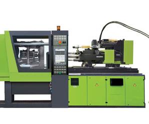
Getting Into LSR: Part II--Chosing an Injection Machine
The criteria for selecting a liquid silicone rubber injection molding machine are very similar to selecting a machine for standard thermoplastic injection molding, with several key differences.


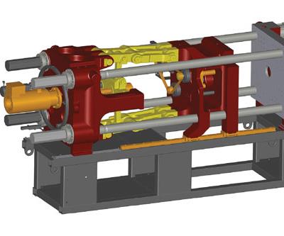
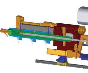
The main differences in a machine for LSR vs. thermoplastics are in the barrel, screw, and nozzle, as well as in mold temperature control and the need for a separate dosing/pumping unit.
Electric toggle clamps (with tiebars or tiebarless) provide more precise opening and closing positions and speeds, advantageous for delicate demolding operations and allowing for injection with the mold partly open to vent air.
Electric injection units cost more but offer greater accuracy than hydraulic systems. Not all LSR applications can take Electric injection units cost more but offer greater accuracy than hydraulic systems. Not all LSR applications can take advantage of that increased accuracy, however.
LSR molding requires a zero-compression screw, water-jacketed barrel, special check ring, and a fast-acting shutoff nozzle.
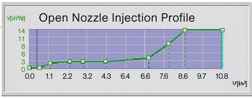
With an open-nozzle LSR cold-runner system, the typical profile (read left to right) starts at maximum injection speed to open all nozzles simultaneously, and tapers downward toward the end of fill.
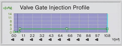
A valve-gated LSR cold-runner system can use a flat profile (read left to right) with whatever injection speed is most efficient to fill the cavities.
The criteria for selecting a liquid silicone rubber injection molding machine are very similar to selecting a machine for standard thermoplastic injection molding, with several key differences. Most of these relate to the heat-curing thermoset nature of LSR, its very low viscosity, and its tendency to expand during cure. Although you can never specify one machine to fit every requirement or opportunity that comes your way, the guidelines discussed in this article will help you specify an extremely versatile machine.


CHOOSING THE RIGHT CLAMP
Let’s start with the clamping unit of the machine. The two most common clamping systems to choose from are hydraulic ram and electric toggle. Each offers its own advantages and disadvantages. Both are available in tiebar or tiebarless design.
The hydraulic clamp has a very simple construction with very few moving parts, as well as closed-loop clamp-force control using a hydraulic pressure transducer to maintain continuous clamp force throughout the process. In addition, the clamp-force setting can be changed without interrupting the process. The hydraulic clamp system offers greater flexibility for mold height, as the entire opening stroke is available for mold installation, and the mold height setup tends to be simpler with this system.
To utilize the advanced processing method of running injection in parallel to clamp-force buildup, a hydraulic machine must be equipped with a double hydraulic pump. Or instead you can use a hybrid machine system with an electric servo-controlled injection unit and hydraulically operated clamp. Either of these options will allow you to maintain a low clamp force during the injection sequence—making the small mold vents used in LSR tooling more efficient—and then increase the clamp force during the holding pressure and curing sequence when it is most important.
The electric toggle clamp provides more precise opening and closing positions for delicate demolding or robot takeoff operations, as well as the ability to implement injection parallel to mold-closing sequences with very precise clamp positioning. This differs from a hydraulic machine with injection parallel to clamp-force build up. The electric system will allow you to close the mold to a precise position with accuracy of better than 0.001 in. before you begin the injection sequence, and then continue mold closing with precise speed—allowing you to remove hard-to-vent trapped air or to eliminate venting completely with very low-viscosity materials. The electric system also can achieve faster dry-cycle times due to its quicker acceleration and deceleration.
One key functional difference between the hydraulic clamp and the electric toggle is how clamp force is monitored. Hydraulic machines monitor hydraulic pressure through a transducer, whereas the electric machine must measure stress on the tiebars or toggle. For this reason, many machine manufactures do not offer closed-loop clamp-force control on electric toggle machines.
SIZING THE CLAMP
The first thing to consider is the most obvious: The platen size must meet space requirements of the mold. Secondly, when specifying a clamping system that utilizes tiebars you need to review the distance between tiebars, and when specifying a tiebarless clamping system you must pay attention to the frame or drop-out width. This specification is particularly important if the parts are going to be brushed out of the mold or ejected and allowed to drop into a chute below the machine. A tiebarless system offers greater flexibility for auxiliary equipment such as core-pulls or robot movements into the molding area.
When specifying the size of clamping unit, it’s most important to remember that the clamp force must be able to overcome the expansion of silicone during vulcanization (curing). The standard rule for silicone is to allow 2 to 3 tons/in.² of projected part area. Additional items to consider for clamp size specification are part cross section and mold construction. Because LSR material expands significantly during cure, you may want to consider higher clamping forces for molding parts with a very thick cross section. For parts with a thin cross section (0.005 to 0.010 in.), such as diaphragms, the opposite is also true. Although such thin parts may have a very large surface area, the expansion of the silicone at such thinness is limited. The rate of expansion can also be controlled, to a certain extent, by processing with lower mold temperatures and extended cure times.
Mold construction must also be taken into account when determining the required clamp force. The clamp force must be high enough to maintain the correct force distribution across the cavity land. This is particularly important to consider when specifying a machine for a multi-cavity mold to produce very small articles. The total surface area of the part may be very small, so you must instead consider the cavity insert size. Also, use of preloaded cavities and/or spring washers may have an impact on the required clamp force. It is best to consult with your toolmaker and machine supplier together. For these reasons, the machine size for LSR molding is most often based on platen dimensional requirements instead of clamp force—which makes the tiebarless design a good option.
INJECTION UNITS
There are many factors involved in selecting the correct injection unit, such as injection pressure limits, shot capacity, and performance requirements. LSR molding can sometimes offer more flexibility in injection-unit size than standard thermoplastic processing, but there are still many details to consider.
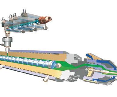
Most of the details that differ between an LSR molding machine and a standard thermoplastic machine relate to the screw and barrel assembly. Because LSR is a thermoset that cures when heated, the injection unit has a water-cooled barrel to maintain consistent temperature of the material during metering and injection and to retard reaction of the material prior to molding. The screw is a zero-compression feed screw equipped with a plate-style, spring-loaded check assembly. The check assembly is designed for positive shutoff of low-viscosity LSR materials, and the spring ensures the plates are in the closed position when static. This means the forward movement of the screw is not required to seat the check assembly, as is necessary with the standard check ring used in thermoplastic molding.
The end of the barrel must be equipped with a shutoff nozzle. Based on faster reaction time, pneumatic operation of the shutoff nozzle is preferred over hydraulic operation. There are many styles and makes of shutoff nozzles available—it is important to understand your application when choosing one. For cold-runner molds, a diving tip is most often used to eliminate introduction of air into the runner system. The diving tip is usually equipped with either a 15- or 25-mm tip with a perimeter seal. This tip penetrates the sprue bushing and can be retracted slightly to decompress the cold-runner system. This small amount of decompression helps avoid leakage in the mold nozzles when using an open-nozzle system. When used with a cold-runner system, this tip can be water cooled—but it is not required. For hot-runner molds (analogous to a cold-runner thermoplastic mold), a 0.5-in.-radius tip is usually used. In this case, water cooling is absolutely required to avoid material curing in the nozzle. This tip is usually retracted after the injection and hold sequence using a sprue-break option.
While most LSR injection machines use a reciprocating screw to help mix the two-component resin system, non-standard injection units can be supplied for special applications. For example, Engel offers a plunger injection unit for highly reactive LSR materials that cannot withstand the shear imparted by the screw. It can also be used with highly abrasive filled formulations. And for very large shots of greater than 500 cc, Engel supplies a double-plunger injection unit in which the materials meet at the end of the barrel and pass through a static mixer just before reaching the nozzle. Machines can also be built for two-component overmolding with both thermoplastic and LSR injection units mounted in parallel or perpendicular arrangements.
Pressure is often disregarded when specifying injection units for LSR because the pressure needed to inject the material and move the flow front is very low. But injection pressure limits definitely should be considered when specifying a machine that will be running a multi-cavity, open-gate, cold-runner system. (A cold runner in thermoset LSR molding is analogous to a hot runner in thermoplastic molding—both keep the material in the runner “live,” which is especially important because LSR is a high-value material.) In this type of system it is important that all gates open at the same time to maintain balanced filling. In an open-nozzle system, gate shutoff is achieved by curing a small amount of material in the gate on each cycle and injecting it into the next part (like a “cold slug” in thermoplastic molding). To achieve the required balance it is important to generate peak injection pressure very early in the injection sequence to ensure that all nozzles open simultaneously. The injection profile would look similar to Fig. 1. (Note that the graph is read left to right.)
You will notice the initial injection sequence is set at the maximum injection speed setting, and then profiled down to a slower speed as it transitions into the hold sequence. Even though the machine probably will not be able to reach the velocity setpoints, this profile will ensure that all gates open at the same time.
In a valve-gated cold-runner system, opening of the valve gates is mechanically actuated, so the ability to generate pressure very quickly is not critical. The injection sequence is based on the ideal speed to maintain flow and fill the cavity in the most efficient manner. The normal LSR injection profile for a valve-gated cold runner would look similar to Fig. 2.
SIZING THE INJECTION UNIT
Shot capacity is where you have the most flexibility in LSR injection machines. Since the LSR screw injection unit uses a zero-compression screw, there are no feeding, melting, or compression zones. Also, LSR molders do not consider residence time when sizing the screw diameter or injection capacity. That’s because the material in the barrel is kept cold and uncured. The main consideration when selecting the correct screw diameter for LSR should be stroke resolution during the injection sequence. Many molders consider the ideal shot size to be 30% to 60% of the total shot capacity; I prefer to consider the stroke of the screw during the injection cycle versus the percentage of the barrel that I am using. You have to calculate the smallest stroke movement that you can use that will still allow the machine to maintain speed and pressure control. This will differ depending on the drive system of the injection unit and how the injection unit is equipped.
The hydraulic injection unit is a standard, proven system with very good repeatability and speed control in both acceleration and deceleration. Also, with the advances in controller scan times and hydraulic hardware, these systems have become more accurate. The performance of the standard hydraulic system can be improved with the addition of a dedicated servo-valve located close to the injection unit; this will reduce the reaction time of the valve and the compression of the hydraulic fluid. Depending on the machine and controller ability, minimum strokes using a hydraulic system can be less than 0.500 in. and still maintain excellent control—this could be as low as 5% to 10% of the total shot capacity.
Compared with the hydraulic version, the electric injection unit provides increased accuracy, with speed and position control, along with increased shot-to-shot repeatability. Whereas the hydraulic injection system measures pressure via a hydraulic pressure transducer and translates this via calculation into actual pressure on the plastic, the electric injection system (in Engel’s case) measures direct injection and hold pressure via a force transducer located on the screw support. This means all pressure readings are absolute and not calculated. The maximum injection rates for the electric machine may not exceed those of the standard hydraulic machine, but the dynamic acceleration and deceleration of the electric unit will outperform the hydraulic system. Startups and parameter changes take less time with the electric injection unit than on standard hydraulic systems because there is no oil to warm up.
Although it sounds as if there is no contest here and you should always choose the electric injection unit, you must consider your application and the capital cost of the equipment. It is true that the electric injection unit will be more accurate than a standard hydraulic system, but it can also add 20% to 30% to the equipment cost. Additionally, due to the compressibility of LSR in the barrel, cold runner, and mold cavity, that increased accuracy is not always realized in fact when molding larger parts and small parts in high-cavitation cold-runner molds. Furthermore, to the extent that energy savings enter into your choice of electric vs. hydraulic machine operation, LSR could offer even greater potential cost savings than with thermoplastics because of the longer cycle times, which mean more idle time in which a hydraulic pump would be running but doing no useful work.
All discussions involving injection molding of LSR eventually come to the topic of micro-molding. Due to the low torque required to meter LSR materials, and the low injection pressures required, it is possible to use screw injection units with diameters as small as 12 mm. This small-diameter screw, coupled with the accuracy of an all-electric injection machine, can permit shot sizes as small as 0.005 in.3.
But in micro-molding, the injection machine is only one factor. The dosing equipment (a separate unit required for all LSR molding) must also be sized appropriately to maintain consistent metering and mixing of small shots. Micro-molding will also highlight deficiencies in the injection mold, so quality tooling will be as important as the molding machine and dosing equipment.
OTHER SPECIAL FEATURES FOR LSR
Other factors important for consistent LSR processing are sufficient mold heating zones and temperature control, a cooling-water manifold and flow control, vacuum pump and vacuum monitoring software, interface for an integrated demolding device, and programmable sequence control.
As consistent mold heating is required to maintain fully automatic processing, the machine should have self-tuning software to optimize the heating profile for the specific mold requirements. The number of mold heat zones should be determined by the toolmaker, based on mold size and mass, to maintain consistent temperatures. As a rule of thumb, the minimum number of zones required for an LSR machine over 50 tons is eight zones. For a smaller machine, four zones are sufficient.
The water cooling for cold-runner systems is extremely important. The temperature and flow rate of the cooling water must be consistent, or curing of the material will also be inconsistent. In open-nozzle cold-runner systems, inconsistent water flow or temperature may cause nozzles to either leak or cure too deeply. It is also a good idea to add a water filter system to ensure clean, uniform flow to the molding system.
The mold vacuum system should have a dedicated vacuum source, vacuum valve, and software to monitor the vacuum level prior to injection. Due to the low viscosity of LSR, venting is very limited, and some materials will flash even with vents less than 0.0005 in. deep. This increases the importance of evacuating as much air as possible prior to injection. Vacuum monitoring software is important to ensure the proper vacuum levels are reached during fully automatic processes.
Owing to the rubbery flexibility of silicone, there are many demolding options that are not available in thermoplastic molding. Because of this many toolmakers have developed simple demolding devices that are integrated right into the mold—from a simple knock-out board or brush system to more complex gripper systems. The machine should have the ability to interface with this device and program it into the molding sequence.
The final piece of the LSR molding cell is the dosing system. As with injection molding machines, there are many options for dosing equipment, ranging from systems that are fed by small reusable plastic cartridges to ones fed by 55-gal drums. Pump operations range from electric servo control to hydraulic and pneumatic operation. Discuss your specific application with one of the industry’s dosing system providers. (Dosing equipment will be covered in the next article in this series.)
About the Author
Steve Broadbent is LSR/elastomer project engineer at Engel Machinery in York, Pa. He joined Engel two years ago after 18 years at three rubber custom molders in jobs ranging from press operator to project engineer. Reach him at (717) 764-6818 or steve.broadbent@engelglobal.com.


Related Content
Foster Adds Specialty TPU and TPU Alloy Products to its Arsenal of Healthcare Materials
AdvanSource Biomaterials’ specialty TPU materials are used in application segments such as cardiology, orthopedics, drug delivery, endoscopy, wound care, urology, and neurology.
Read More
Partnership Develops TPEs with Reduced Carbon Footprint
Teknor Apex and Israel’s UBQ Materials have jointly developed new line of Teknor sustainable TPEs.
Read More
Tracing the History of Polymeric Materials, Part 25: Silicones
The long road to the development of silicone resulted in a chemistry that is remarkably versatile.
Read More
Tracing the History of Polymeric Materials -- Part 29: Polyurethane
This material family has unparalleled versatility, not only in terms of the forms the material can take, but in the different ways in which it can be processed.
Read MoreRead Next

Getting Started in LSR: Understanding the Materials, Part I
Liquid silicone rubber (LSR) injection molding is a long established process but it is enjoying an upsurge in interest for medical, automotive, infant care, and general industrial applications.
Read More
LSR Part III-- Choosing a Mixing/Metering System
Liquid silicone rubber (LSR ) is a two component reactive chemical with a viscous, paste-like consistency.
Read More
Why (and What) You Need to Dry
Other than polyolefins, almost every other polymer exhibits some level of polarity and therefore can absorb a certain amount of moisture from the atmosphere. Here’s a look at some of these materials, and what needs to be done to dry them.
Read More