How to Collect and Interpret Extrusion Process Data; Part 3
In this final installment, learn how process data can be used to identify and fix extrusion issues.
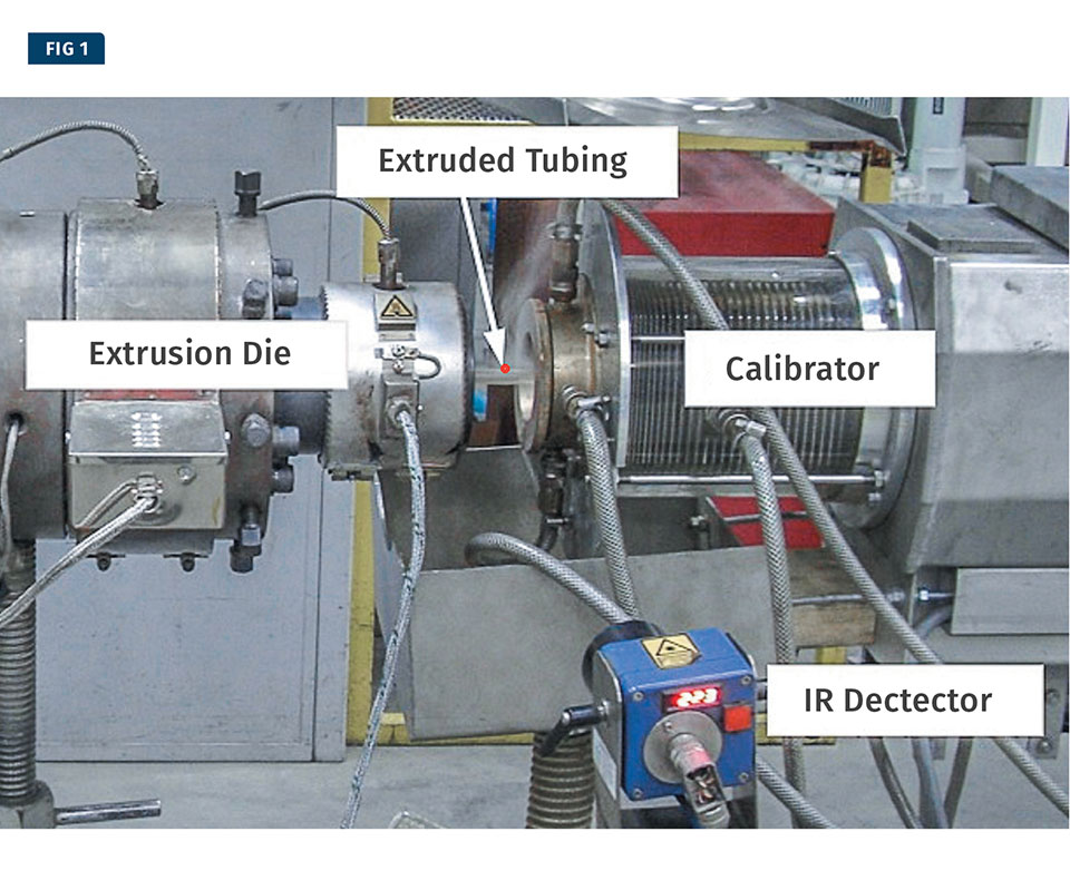
This single-screw tubing line is using an infrared temperature-measurement probe.
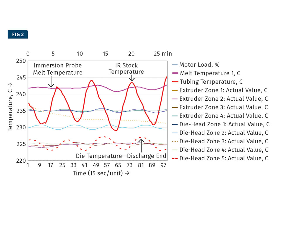
Process data from the line shown in Fig. 1. The trend plot shows temperature measured in 11 locations, as well as motor load. Note a number of temperatures with a regular sinusoidal variation with the same frequency. The tubing temperature shows the largest variation, which is a problem. The cause? Variation in the feed material entering the extruder.
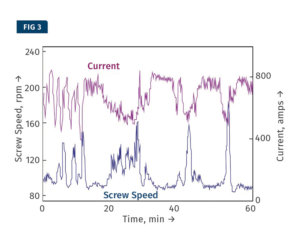
Pressure is generally controlled with a feedback control to the screw speed. But pressure feedback does not work for rapid changes in pressure, which will result in rapid variations in screw speed and motor current, as shown here. The issue here turned out to be scale buildup in cooling channels.
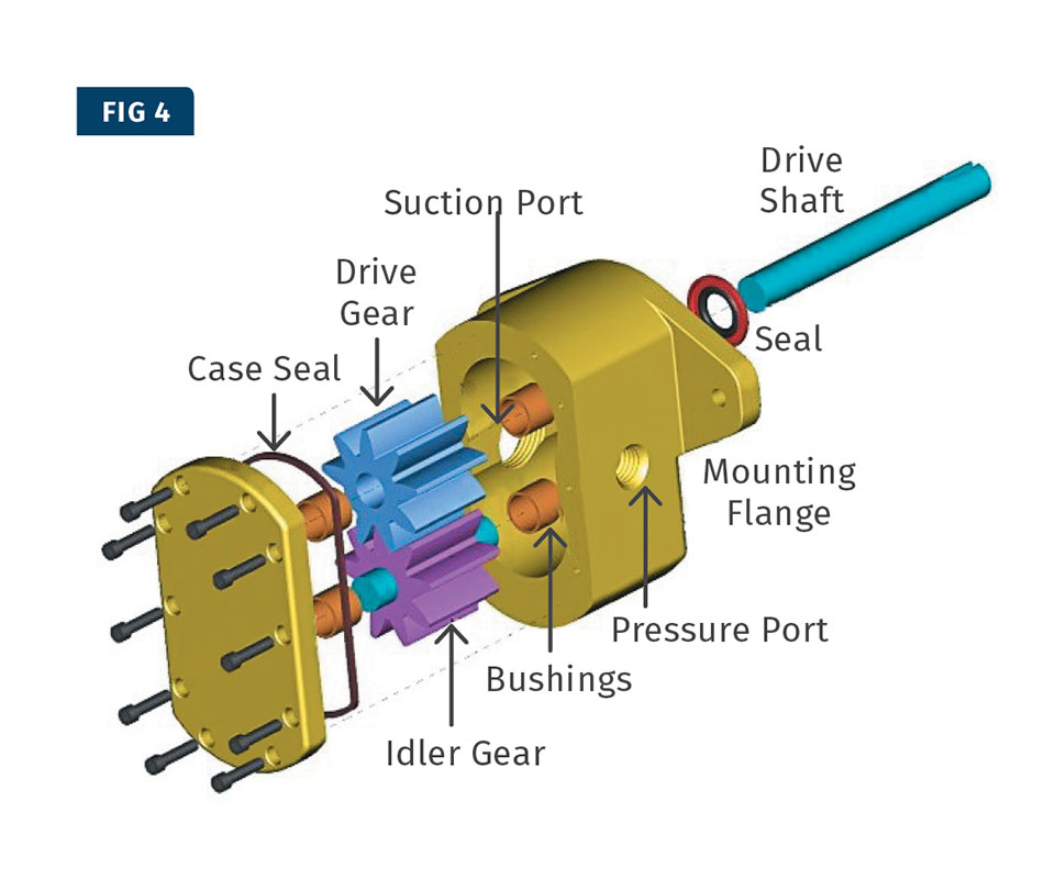
Gear pumps are used to closely control the flow from an extruder to achieve less variation in flow rate and extrudate dimensions. At the discharge end of the gear pump, the polymer melt is expelled by the intermeshing action of the gears.
The intermeshing action of a gear pump creates both short- and long-term pressure fluctuations. The latter must be investigated and solved. The pressure pulsing of the teeth of a gear pump can be reduced by using helical gears rather than straight gears.
The discharge pressure on a new extruder just put into service showed a regular sinusoidal variation.
The barrel temperatures also showed a regular sinusoidal variation. The trend plot shows that the variation in barrel temperature is much too large, suggesting poor tuning of the temperature controllers for the barrel zones.
Barrel temperatures can be optimized to achieve the lowest pressure fluctuation. This can be done by changing the setpoint and following the transient response of the extruder. This shows the transient response from changing the setpoint of barrel zone 1 from 100 C to 175 C. This figure shows the pressure vs. the actual temperature of zone 1.


Many modern extrusion lines are equipped with data-acquisition systems (DAS). These systems can present extruder operators and process engineers with a large amount of data. There are several critical issues in the Engineering Inc. proper use of a DAS:
• Are the correct process variables measured and monitored?
• Is the data collection rate appropriate?
• Is operating personnel capable of properly interpreting the data?
The first installment focused on the proper use of a DAS. The second installment focused on melt temperature. In this third and final installment of this series, the discussion will focus on how process data from a DAS can be used to detect and solve extrusion problems.
VARIATION IN STOCK TEMPERATURE
Figure 1 depicts a single-screw line extruding tubing. The temperature of the extrudate is measured with an infrared (IR) thermometer. Only a short section of the tubing is visible between the die and the calibrator. Process data was captured and plotted (Fig. 2).
The trend plot shows temperature measured in 11 locations; it also shows the motor load. There are four extruder zones and five diehead zones. The temperature measured in these zones is the temperature of the metal. Polymer melt temperature is measured with an immersion probe in the die and with an IR detector just beyond the exit of the die.
The trend plot shows a number of temperatures with a regular sinusoidal variation with the same frequency. The cycle time of the variation is about 6 min. The amplitude of the temperature variation varies considerably from 2° C up to 15° C (3.6 to 27° F). The IR measurement of tubing temperature after the die shows the largest variation (15° C/27° F). The melt-temperature variation measured with the immersion probe shows significantly less variation (2-3° C/4-5° F). The variation in tubing temperature is unacceptably large and indicates a problem.
The die temperature at the discharge end varies about 4°C (7° F), and it would be tempting to conclude that the die- temperature variation is causing the tubing-temperature variation. However, this is not possible because the tubing- temperature variation is about three to four times greater than the die-temperature variation. Clearly, the die-temperature variation is caused by the melt-temperature variation and not the other way around. A similar argument can be used for the variation in barrel temperatures.
There is little variation in motor load and no variation in screw speed. As a result, the tubing-temperature variation cannot be caused by changes in viscous dissipation. This leaves one other possible cause of the problem: variation in the feed material entering the extruder. Unfortunately, this extruder was not equipped with a pellet temperature sensor in the feed port. However, there was strong indirect evidence of pellet temperature variation. The polymer was dried before it was conveyed to the extruder. It turned out that the feed hopper was filled with hot, dry material every 6 min.
The feed hopper itself was not heated. Therefore, the hot pellets from the drier would cool down in the feed hopper as they made their way to the feed opening of the extruder. The hopper was filled at 6-min intervals. This created a 6-min cycle in the temperature of pellets entering the extruder. Once the cause of the problem is known, the solutions are obvious. One possible solution is to install a hopper drier on the extruder so that the pellets stay dry and at constant temperature in the hopper.
It should be noted that the problem would have been noticed immediately if the extruder had been equipped with a pellet temperature sensor at the feed opening of the extruder. Such a temperature sensor provides important information. Unfortunately, extruder manufacturers generally do not provide a temperature sensor in this part of the machine.
VARIATION IN FEED-HOUSING TEMPERATURE
The extruder performance is dependent on the temperature of the feed housing. Thus, it is important to measure that temperature, but surprisingly, many extruders do not have a temperature sensor in the feed housing. That housing is generally water cooled because it is located up against the hot extruder barrel. Water cooling allows the feed housing to be maintained at temperatures much lower than the barrel temperatures. In most extrusion operations, the barrel temperatures are quite high (over 150 C/302 F).
If the feed housing cannot be maintained at a low enough temperature, extruder performance can deteriorate quickly. This can lead to unstable extrusion conditions. A high level of instability is called surging.
Surging caused by overheating of the feed housing was discussed by J. Powers et al. at the Society of Plastics Engineers 2000 Annual Technical Conference (ANTEC). The overheating caused large variation in motor current, screw speed, and pressure in a large vented extruder. The pressure was controlled with a feedback control to the screw speed, which was varied to maintain constant pressure. However, this pressure-feedback control only works when the pressure changes very slowly and gradually. Pressure feedback does not work for rapid changes in pressure, which result in rapid screw-speed variation. The variation in motor current and screw speed is shown in Fig. 3.
The variation in screw speed and motor current are quite severe. The screw speed varies between 80 and 160 rpm with a variation in motor current from 400 to 800 amps.
Calcium deposits in the cooling channels of the feed housing will reduce heat transfer and lead to higher temperatures. It is important to measure the inlet and outlet temperatures and the flow rate of the water. With these three data points, the amount of cooling can be quantified. If the amount of cooling declines over time, this is likely caused by calcium deposits.
The problem of scale buildup in cooling channels is quite common. Calcium scale is a hard, thick coating of calcium carbonate that forms on the internal walls of cooling channels. Water that contains minerals that cause scale is called “hard” water. It is important to make sure that the water is properly treated with a water softener to avoid scale buildup. There are other ways to prevent scale, such as use of an electronic water descaler.
For water cooling of the extruder feed housing it is good practice to use a closed-loop circuit. This reduces the chance of getting hard water in the cooling system. This applies not only to the water-cooled feed housing but also temperature zones along the extruder barrel that employ water cooling.
VARIATION IN MELT PRESSURE
In the first part of this article we discussed how the screw flight creates a sawtooth pattern in the melt pressure measured at the discharge end of the extruder. A similar situation occurs with a gear pump (Fig. 4). Gear pumps are used to closely control the flow from an extruder in order to achieve less variation in flow rate and extrudate dimensions.
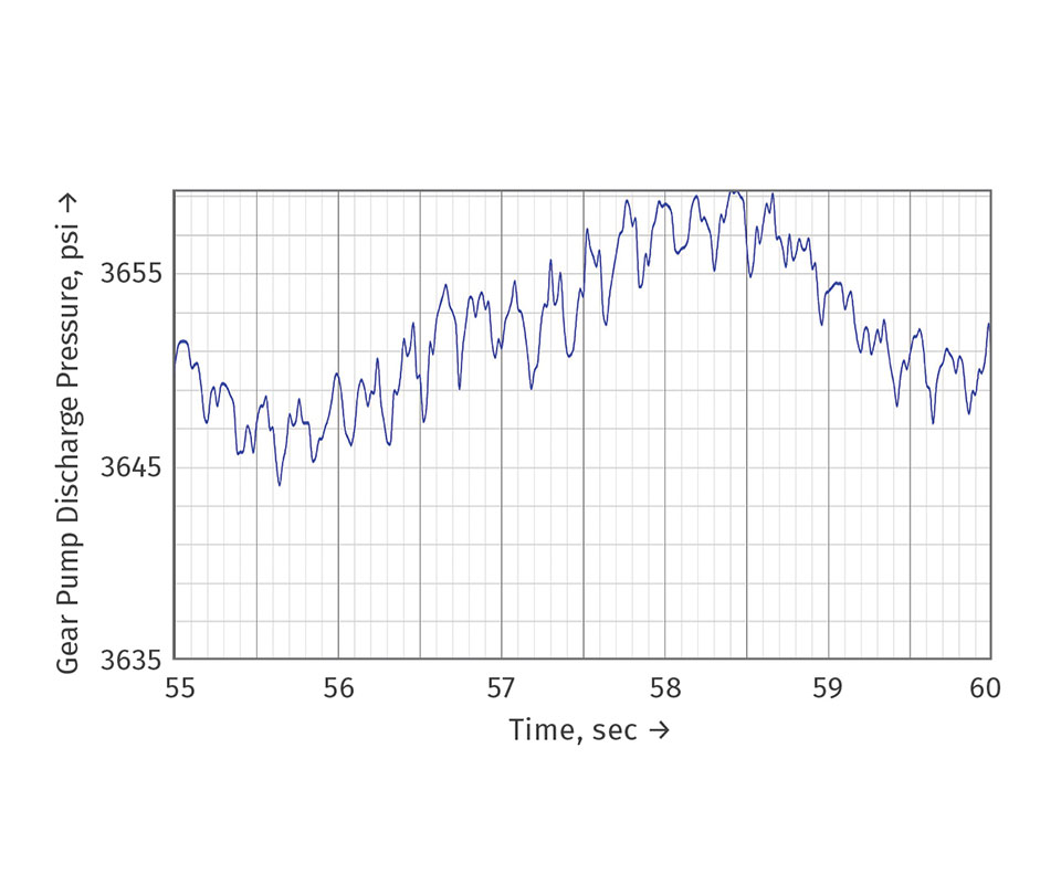
At the discharge end of the gear pump, the polymer melt is expelled by the intermeshing action of the gears. This creates pressure pulses as shown in Fig. 5. This figure shows short-term fluctuations at about 4-5 pulses/sec caused by the meshing of the gear teeth. The pressure pulses from the gear teeth are small (about 4-6 psi) but clearly distinguishable. The figure also shows longer-term fluctuations with a cycle time of about 10 sec and with amplitude of about 10-12 psi. The source of the longer-term fluctuation was not known; however, this fluctuation certainly should be investigated and eliminated if possible. The pressure pulsing of the teeth of a gear pump can be reduced by using helical gears rather than straight gears.
CYCLIC VARIATION IN DISCHARGE PRESSURE
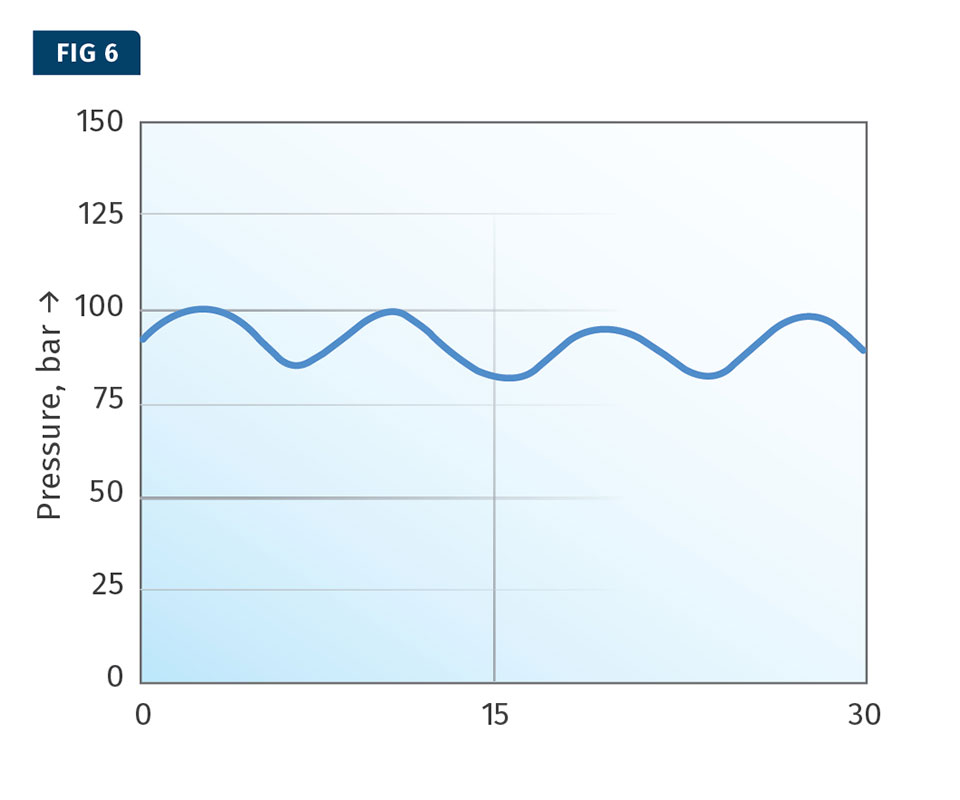
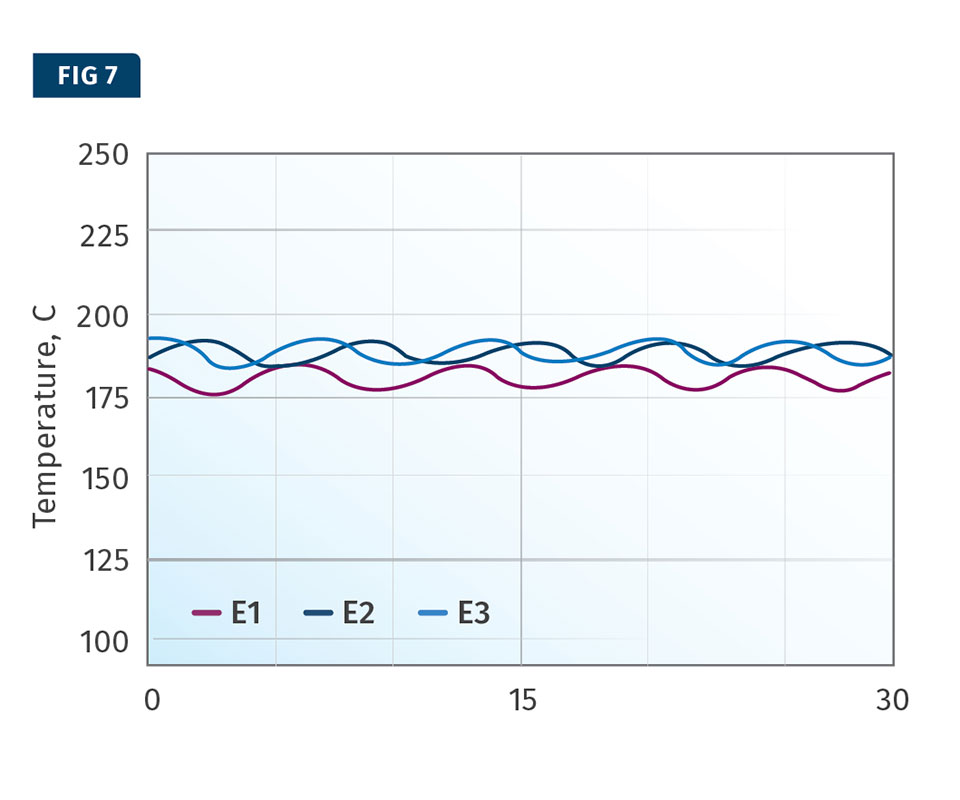
The last example deals with a new extruder whose discharge pressure showed a regular sinusoidal variation, as shown in Fig. 6. The barrel temperatures also showed a regular sinusoidal variation (Fig. 7).
The barrel-temperature trend plot shows that the variation in barrel temperature was much too large—about 10-15° C (18-27° F). This suggested poor tuning of the temperature controllers for the barrel zones. When the tuning was corrected, the barrel-temperature variation reduced to normal levels and the pressure variation reduced from ±10% to about ±0.7%.
PROCESS OPTIMIZATION
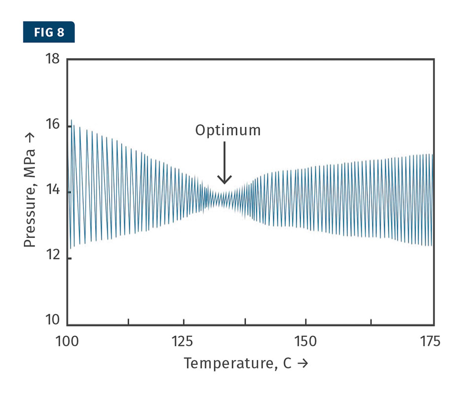
Data-acquisition systems are also very useful for process optimization. For instance, barrel temperatures can be optimized to achieve the lowest pressure fluctuation. This can be done by changing the setpoint and following the transient response of the extruder. Figure 8 shows the transient response of changing the setpoint of barrel zone 1 from 100 C to 175 C (212 to 347 F). This figure shows the pressure vs. the actual temperature of zone 1.
This figure shows clearly that the pressure fluctuation reaches a minimum at a temperature of about 130-135 C (266-275 F). These results indicate that the optimum temperature of barrel zone 1is around 130-135 C. Since the pressure versus temperature can be displayed in graphical form, determination of the optimum temperature is quite easy.
These examples show that a DAS is very helpful in detecting process problems and in troubleshooting these problems. A DAS is also very helpful in process optimization, as the example indicates.
ABOUT THE AUTHOR: Dr. Chris Rauwendaal is a well-known author, lecturer, researcher, entrepreneur, and consultant in the field of extrusion. He holds numerous patents and has written more than 200 articles and seven books related to extrusion, mixing, injection molding, and statistical process control. A Fellow of the Society of Plastics Engineers (SPE), he is the developer of the CRD, VIP, and ASM mixing technologies that utilize strong elongational flow to improve mixing in extrusion and molding. Rauwendaal also developed the HHT (high-heat-transfer) extruder screw designed to improve cooling in foam tandem and other extrusion operations. In 1990 he founded and is still president of Rauwendaal Extrusion Engineering. Contact: (530) 269-1082; chris@rauwendaal.com; rauwendaal.com.
Related Content

The Importance of Viscosity in Melting
The calculations required to determine the right melt temperature for each polymer are complicated. Knowing the power-law coefficient and the consistency index of the polymer you run might prove useful.
Read More
How to Estimate and Control Head Pressure
You rightfully worry about melt temperature, but don’t overlook head pressure, because the two are closely linked and will influence line performance.
Read MoreWhy Compression Ratio is Important
Compression ratios have been pretty much standardized over the years, based on what has typically worked before. But there are quite a few variables that must be considered in order to get the optimum performance from your screw.
Read More
Fully Automated Extrusion Process Enables Use of Composites for Manufacturing Pressure Tanks
Amtrol was looking for a more cost-effective means to produce thin-wall liners for a new line of pressure tanks. With the help of a team of suppliers, they built one of the world’s most sophisticated extrusion lines.
Read MoreRead Next

How to Collect & Interpret Process Data in Extrusion
The first installment of this three-part series focuses on proper use of a data- acquisition system.
Read More
Lead the Conversation, Change the Conversation
Coverage of single-use plastics can be both misleading and demoralizing. Here are 10 tips for changing the perception of the plastics industry at your company and in your community.
Read More
How Polymer Melts in Single-Screw Extruders
Understanding how polymer melts in a single-screw extruder could help you optimize your screw design to eliminate defect-causing solid polymer fragments.
Read More