
Injection Molding Troubleshooter: Common Mistakes in Long-Fiber Molding
As the superior mechanical properties of long-fiber compounds attract growing popularity among OEM designers, an increasing number of injection molders are being introduced to these materials for the first time.

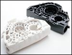
Burnoff of resin shows the glass skeleton typical of long-fiber parts. (Shown here: a seatbelt pretensioner housing of Verton 60% long-glass reinforced nylon 66.)
As the superior mechanical properties of long-fiber compounds attract growing popularity among OEM designers, an increasing number of injection molders are being introduced to these materials for the first time. Proper handling and molding of long-fiber reinforced thermoplastics is not rocket science. However, it’s also not the same as molding conventional short-fiber compounds, so experience in molding short glass fibers may not translate accurately to molding long glass. If you want to avoid the most common errors in long-fiber molding—from materials handling all the way to the mold cavity—keep in mind this fundamental principle: You must preserve the fiber length in order to retain the benefits of using long glass in the first place.


Mistake #1
Rough and tumbleconveying
Many molders are apt to mistreat long-glass materials right out of the box. As compared with standard 1/8-in.-long short-fiber pellets, long-fiber pellets are cylinders 10-12 mm (0.39 to 0.47 in.) long or longer. Although they typically have a resin-rich surface, they can have 4000 or more cut glass filaments exposed on the ends. The higher stiffness and momentum of the larger pellets make them considerably more abrasive than short-glass pellets when they hit walls of conveying equipment. (By the way, the reverse is true in the melt phase: Contrary to popular belief, molten long-fiber materials are less abrasive than short-fiber compounds because there are fewer cut ends for the same glass content.)
Another important point is that even properly wet-out long-glass pellets can fracture when they hit the walls of conveying hardware, generating loose glass fibers or fines.
So here’s what to do: Keep conveying distances as short and straight as possible. Convey the pellets as slowly as possible. Use wear-resistant stainless or hardened steel conveying equipment, especially in bends or elbows. Don’t use flexible tubing on bends. Even coated aluminum can wear out too fast. Long-radius sweeps for bends and elbows will also help minimize wear.
Mistake #2
Built-in clogging and bridging
Molders often use conveying lines of less than 2 in. diam. But remember that long-fiber pellets are longer than standard pellets. So for clog-free flow and reduced wear, use conveying lines of at least 2 in. diam.—2.5 in. is even better. For pellets longer than 12 mm, conveying lines should have 3 in. minimum diameter.
Likewise, pick-up wands should have at least 2 in. diam. and 3 in. or larger for pellets longer than 12 mm. Use single-tube wands with air-bleed holes. Wands with outer telescoping tubes over an inner tube don’t work well: They’re hard to push into long pellets and the pellets tend to block air flow.
Flat-bottom dryer hoppers encourage bridging and degradation of long pellets. All hoppers should have conical bottoms with at least 45° discharge angle (60° is better).
Dryers and holding bins often have small take-off boxes that hold a couple of cups of material—another likely site for bridging. Instead, we recommend a 12-in. cube with the take-off tube mounted at a right angle to the hopper/bin discharge, 4 in. above the bottom of the box and at least 2 in. from the sidewalls.
Typical hopper magnets can also impede flow of long fibers and induce bridging. Make sure there is at least 0.75 in. minimum distance between magnets or between a magnet and the hopper wall.
Mistake #3
Too-small loaders
Some molders like those tiny “just-in-time” loaders that hold a cup or two of material. But they require frequent, rapid refills, which means more conveying cycles and faster tubing wear, as well as high conveying speeds that can shatter long-fiber pellets.
Mistake #4
Maintenance-prone filters
Hopper loaders should not have any filter media and should employ minimal cyclonic flow during filling. Filters are generally designed for dust, not long glass fibers, which can pierce paper filters like arrows, blowing out into the plant or sticking fast so they won’t dislodge during blowback cleaning cycles. Some hopper loaders have screens under the filters. A mat of loose fibers can accumulate on the screen over time and then fall off and plug the feed throat of the machine.
We recommend conveying systems with a central vacuum pump and cyclonic filtration of the air stream to the pump, as well as enclosed filter-cartridge media.
Mistake #5
Undersized injection units
Molding-machine screws and barrels should not be less than 50 mm (2 in.) diam. This minimum leaves adequate clearance and depth in the feeding and compression sections of the screw, so as to ensure steady feeding of long pellets and minimize glass breakage in the compression section.
With respect to feeding, the safety pin across the feed throat (required by a new ANSI standard) can cause bridging in small barrels but shouldn’t be a problem with barrel diameters of at least 50 mm.
Molders can also run into trouble if the machine’s shot capacity is undersized. If there’s only one shot in the barrel, high screw speeds are needed to completely refill the barrel on each shot. That means high shear and consequent fiber breakage, destroying the benefits of long fibers. To keep screw speeds low, use a barrel that can hold three to four shots. Use the entire cooling time to plasticate the next shot. Keep backpressure low and set the temperature profile higher than normal. Melt the resin using conductive heat rather than shear.
Mistake #6
Wrong screw
A number of injection machine suppliers nowadays supply barrier or mixing screws as standard equipment. However useful these may be in many applications, they are harmful to long-fiber compounds since they break up the fibers. What you need is a plain old “general-purpose” screw with 20:1 to 24:1 L/D and compression ratio of 2:1 to 2.5:1.
If you have a ball-type check valve, you’re going to get glass breakage and reduced mechanical properties. Use only a free-flow screw tip and ring-type check valve.
Mistake #7
Long, narrow nozzles
Keep nozzles as short as possible with a wide flow path—almost equal to the sprue diam. No mixing nozzles or melt filters allowed.
Also avoid shutoff nozzles whenever possible. We recommend one-piece nozzles rather than the common two-piece type with a removable tip. The latter are not “idiot-proof,” and plant personnel can mistakenly put a smaller tip on an adequately sized nozzle.
Mistake #8
Restricted flow paths in the mold
Sprues, runners, and gates are often too narrow for long-fiber compounds. Tight radii on runner bends are also deleterious to glass length. Make all of these as large as possible. Large flow paths are necessary to accommodate slow injection, which induces less shear thinning.
The same goes for gates—we recommend 2.5 mm (0.1 in.) minimum with hardened, replaceable gate inserts. Tunnel gates and valve gates are not recommended.
Fat sprues mean you may have to use pneumatic shears for degating—or, better yet, use hot runners, which will eliminate degating and also save on regrind.
LNP Engineering Plastics, Inc. (a GE Plastics Company) in Exton, Pa., produces Verton long-fiber reinforced thermoplastics. Matt Miklos is global Verton business leader; Rick Gregory is global Verton technology manager.


Related Content

Research Suggests Path From Waste Plastics to High Value Composites
Flash joule heating could enable upcycling of waste plastic to carbon nanomaterials.
Read MoreRead Next

Understanding Melting in Single-Screw Extruders
You can better visualize the melting process by “flipping” the observation point so that the barrel appears to be turning clockwise around a stationary screw.
Read More
Why (and What) You Need to Dry
Other than polyolefins, almost every other polymer exhibits some level of polarity and therefore can absorb a certain amount of moisture from the atmosphere. Here’s a look at some of these materials, and what needs to be done to dry them.
Read More