Tooling: Reducing the Mass In Sprue Bushings
Important and frequently overlooked details of sprue-bushing design can improve the process and profits for an injection mold.

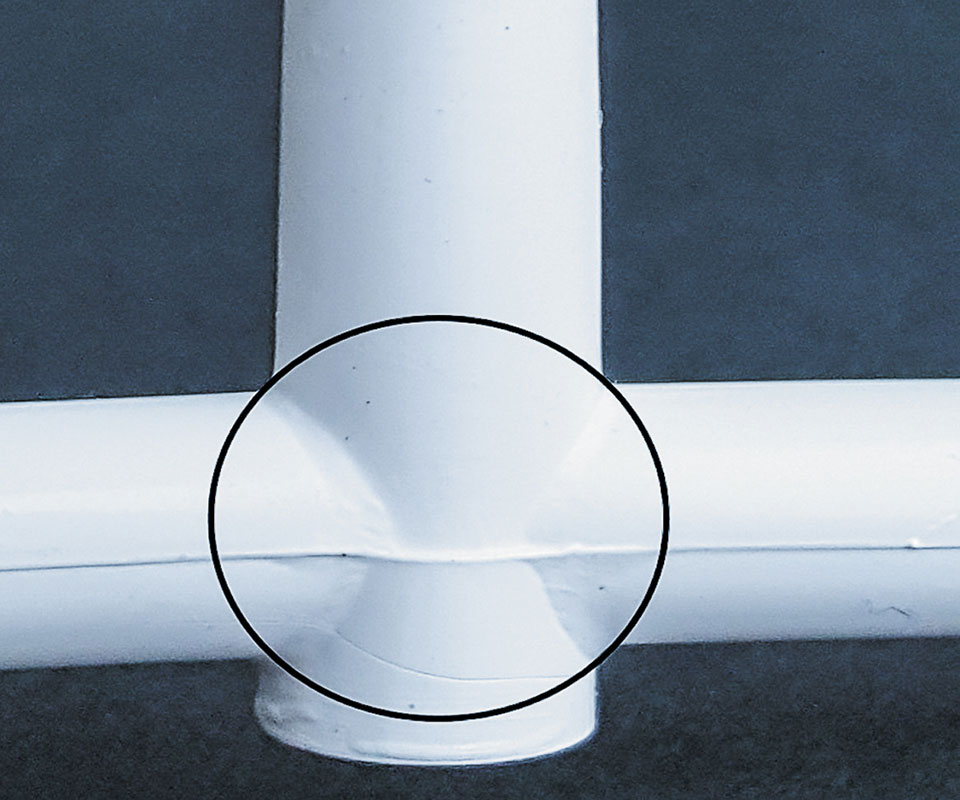
The most massive area of a 2-plate mold is typically at the intersection of the sprue, runner, and cold well.
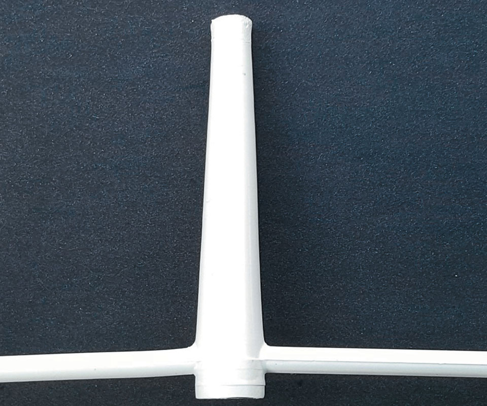
Shallow-tapered sprue bushings can reduce cycle times.
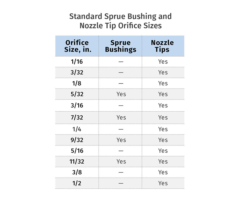
American standard nozzle tips come in 12 different orifice sizes, but sprue bushings are only available in four sizes. It’s not too expensive to ream and polish a sprue- bushing orifice larger, but you can’t make it smaller. Wouldn’t it be nice if someone sold a sprue bushing with a 3/32-in. orifice?
Oversized sprues waste material, time, and money.
Undersized sprues can cause sink and warp.


Sprue bushings are available in more than a dozen different types and styles. Most mold designers select the “B” series bushings because the 7/8-in. head thickness is often the same thickness as the injection clamp plate and it works nicely with standard locating rings. Then they select the nozzle seat radius, one of the four available orifice sizes, and the overall length. That’s often the extent of the consideration given to the sprue bushing during the mold-design phase.
The most massive area in the melt-delivery system of a two-plate mold is almost always at the parting line where the sprue, runner, and cold well intersect. This mass frequently—and often unnecessarily—controls the cycle time. The contribution of the sprue bushing to this massive area is directly related to its internal taper, length, and orifice size.
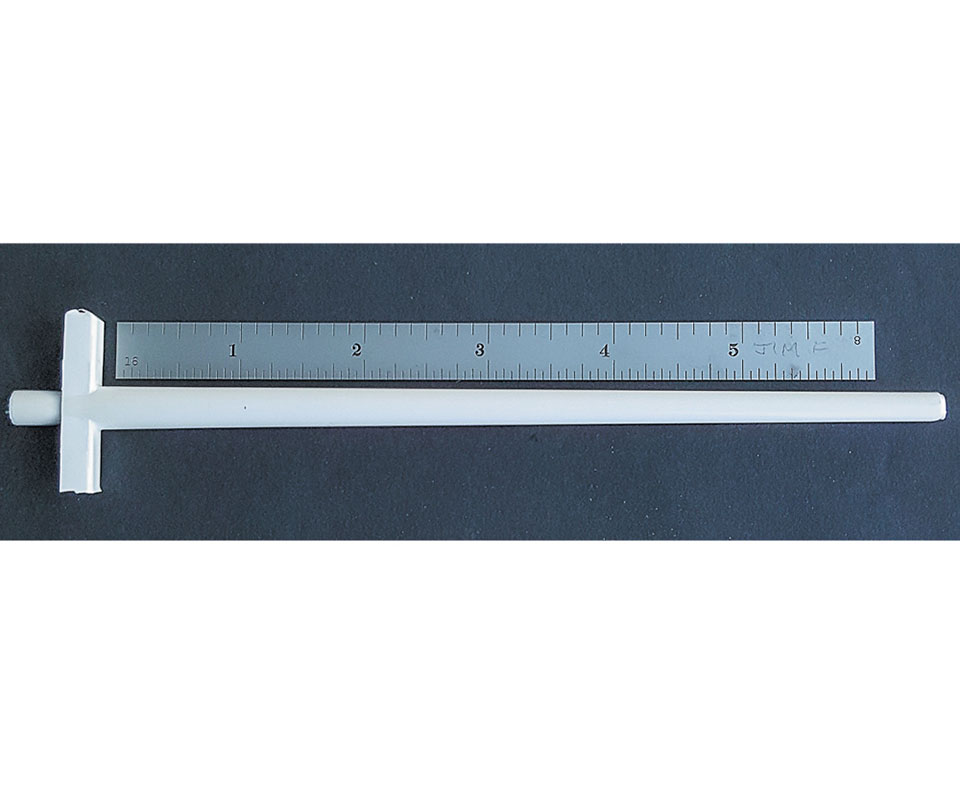
Length: With the industry-standard taper, if you can reduce the length of the sprue bushing by just one inch, you reduce the wall thickness of the sprue at the parting line by 0.042 in. That may not sound like a lot, but thermoplastics are good insulators and they have non-linear ratios of thickness to cooling time. For example, a 0.050-in.-thick part may solidify in 10 sec, but a 0.100-in.-thick part may take 25 sec—not 20.
It may sound strange, but it is more important to reduce the length of a sprue bushing having a small orifice then it is with one having a large orifice. For example, reducing the length of a sprue bushing from 6 in. to 5 in. reduces the area at the parting line by 24% for a small 5/32-in. orifice, but only 16% for a larger 11/32-in. orifice. Most people assume the opposite and only focus their attention on large sprues.
There are a few other mold-design considerations to think about when trying to reduce the length of a sprue bushing, such as:
a) The locating ring may need to be an “Extension Type” (see my March column);
b) You can pick up 1⁄4 in. just by using an “A” series sprue bushing with its 5/8-in.-thick head instead of a “B” series with its 7/8-in.-thick head;
c) Never let the head of the bushing seat directly against the back of a cavity block, runner bar, or any other mold insert, unless the insert can be sufficiently retained with heels and /or multiple large screws.
d) The head of the bushing should be supported by at least 3/8 in. of mold-base steel for small molds and 5/8 in. of mold-base steel for large molds.
Internal Taper: Back in the 1800s, the Brown and Sharpe Co. invented a taper with an included angle of 1⁄2 in./ft for end mills, collets, and machine-tool spindles. More than 150 years later, this is still the adopted industry-standard taper for sprue bushings in injection molds. This taper equates to an angle of 2.39° included, or 1.19° per side. Personally, I would prefer that sprue bushings were sold with a 1/8-in. through hole and allow the tool maker to machine a suitable taper with an ideal orifice size, based on the parts and material to be molded. As it stands now, there’s little choice on the internal angle and only four choices on the orifice size (see table).
Standardization of mold components has greatly helped our industry reduce costs and lead times. But in the case of items such as sprue bushings, I believe it has in part hampered the mold designer’s ability to design a better mold.
Material manufacturers recommend using large tapers in sprue bushings. That makes sense because they’re in the business of selling material. While it’s true that large sprue tapers are less likely to cause a sprue to stick inside a bushing, if you incorporate some key features in the design and construction stages, large tapers are not always necessary.
Two parts having a conical fit with a taper of 7° per side or less are considered to be a “self-locking” or “self-holding” taper. That’s the angle where the coefficient of friction between the two surfaces is greater than the retraction force required to separate them. The smaller the angle, the more the force. Obviously, a sprue bushing with its small internal taper is theoretically self-locking, but we rely on the plastic material to shrink away from the bore of the bushing as it cools—negating this taper lock.
As I noted in my February column, material suppliers specify the shrinkage factor of their materials based on ASTM D955, which uses a 1/8-in.-thick test bar. What many suppliers neglect to mention is that if you are molding something thinner than 1/8 in. it will shrink less than the specified shrinkage factor. Conversely, if you are molding something thicker than 1/8 in., it will shrink more. It doesn’t matter if it’s a part or a sprue—plastic is plastic, and these shrinkage differences apply to both. Since sprues are typically the thickest molded component, the amount of shrinkage is going to be greater, as is the likelihood of negating the taper lock. Therefore, smaller internal tapers, such as 1°, 0.75°, or even 0.5° per side can usually be accommodated without any difficulties. And the cost savings can be considerable. For example, reducing the internal taper from the standard 2.39° included angle down to 1.5° for a 6-in. sprue bushing with a 5/32-in. orifice diameter reduces the diameter of the sprue at the parting line by 23% and the area by 41%. It also reduces the weight of the sprue by 32%.
Orifice Size: Oversized sprue-bushing orifice diameters waste material, time, and money. So how do you determine what size the orifice should be?
Ideally, the area of the sprue-bushing orifice should be approximately equal to the total area of all the gates combined. Ignoring this is a common mistake and often the reason why it takes a lot of injection pressure to go through a sprue bushing—robbing you of additional pressure to pack out the cavities.
Let’s say a fill rate of 1 in.3/sec is needed to fill each cavity in an eight-cavity mold. The amount of material flowing through the sprue orifice is therefore eight times that amount, or 8 in.3 /sec. Depending on the material type, if the sprue orifice is under- sized, you will generate not only a large pressure drop, but also a significant amount of shear heat, which can cause the material to degrade and burn. This increased degradation also generates more material outgases, which can accelerate the clogging and erosion of the vents in the mold.
Assume the part in the eight-cavity mold above has a uniform wall thickness of 0.090 in. Depending on the material type, you might start out with the depth of the gate to each part being two-thirds of the wall thickness, and the width being twice the depth, or in this case, 0.060 in. deep × 0.120 in. wide. The total area of each gate is 0.060 × 0.120 = 0.0072 in.2. The total area of the eight gates combined is 0.0072 x 8 = 0.058 in.2. When you divide this area by the constant 0.7854, and then take the square root, you get an equivalent diameter of 0.271 in. Therefore, a standard 9/32-in. sprue-bushing orifice would work nicely in this example.
When selecting the orifice size for parts that are direct sprue gated, I like to think of what size I would use if it was edge gated, because the bushing orifice is effectively the gate. I then calculate the area of that gate and convert it to the equivalent diameter. For the part above: 0.060 x 0.120 in. gate = 0.0072 in2. That converts to about a 3/32-in. sprue-bushing orifice.
The examples above are intended to help you estimate the best sprue-bushing orifice size, so as to prevent excessive shear and injection pressure. But we are also concerned about reducing the mass of plastic at the parting line. If the material has a low viscosity, such as with many unfilled nylons and polyolefins, you may not have an issue using a smaller sprue orifice. Finite-Element Analysis (FEA) can help predict whether the orifice size will be a problem or not. In lieu of that, it is often a good idea to start off with a slightly smaller orifice. If you end up fighting sink, burns, or high peak pressures during the initial mold sampling, you can always increase the steel-safe orifice size later.
Reducing a sprue bushing’s overall length, internal taper, and orifice size can drastically reduce the mass of plastic at the mold’s parting line. These improvements reduce the weight of the sprue and often the cycle time.
ABOUT THE AUTHOR: Jim Fattori is a third-generation injection molder with more than 40 years of molding experience. He is the founder of Injection Mold Consulting LLC, and is also a project engineer for a large, multi-plant molder in New Jersey. Contact jim@injectionmoldconsulting.com; injectionmoldconsulting.com.
Related Content

Cooling Geometry and the Reynolds Calculation
The original Turbulent Flow Rate Calculator worked well with a round circuit diameter, such as a drilled passage, but not as well using hydraulic diameters. Here’s how the problem was fixed.
Read More
The Impact of Hydraulics on Tool Design -- Part 1 of 2
Get a better understanding of their use, proper sizing, and how the tool design and setup in the machine can impact failures in manufacturing.
Read More
Back to Basics on Mold Venting (Part 2: Shape, Dimensions, Details)
Here’s how to get the most out of your stationary mold vents.
Read More
Why Shoulder Bolts Are Too Important to Ignore (Part 1)
These humble but essential fasteners used in injection molds are known by various names and used for a number of purposes.
Read MoreRead Next

Hitting the Numbers, Part 2: The Shrinkage Factor
The shrinkage factor is one of the most critical numbers to hit.
Read More
Understanding Melting in Single-Screw Extruders
You can better visualize the melting process by “flipping” the observation point so that the barrel appears to be turning clockwise around a stationary screw.
Read More
Advanced Recycling: Beyond Pyrolysis
Consumer-product brand owners increasingly see advanced chemical recycling as a necessary complement to mechanical recycling if they are to meet ambitious goals for a circular economy in the next decade. Dozens of technology providers are developing new technologies to overcome the limitations of existing pyrolysis methods and to commercialize various alternative approaches to chemical recycling of plastics.
Read More