Balanced Filling Is Critical for Holding Molding Tolerances
Processors face a multitude of challenges whenever they approach an injection molding machine.
.jpg;width=70;height=70;mode=crop;format=webp)


Plastics change viscosity in response to shear. Multicavity molds are prone to numerous causes of shear variations in the tool.
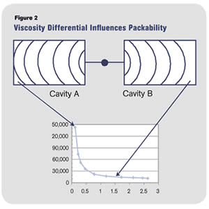
If cavity A fills before cavity B, its melt stops flowing before packing and thus its viscosity is much higher and resistant to packing.
Processors face a multitude of challenges whenever they approach an injection molding machine. One that has persisted for years (decades, actually) is the difficulty of getting multicavity tools to produce identical parts. While the financial benefit of multicavity production cannot be denied, rarely has the full financial benefit been realized. In many cases, the quality problems are so great that single-cavity production can actually be less expensive. So what is the problem with multi-cavity tools? Logic indicates that all one has to do is to geometrically balance the runners. Moldmakers do a pretty good job of this, but the problem persists nonetheless.
A brief thought experiment or study in polymer flow may shed light on root causes. As an example, let us follow the sequence of filling and packing in a two-cavity hot- or cold-runner mold. The runner is balanced with identical gate diameters and identical steel dimensions for each cavity. A short shot shows that the polymer fills the sprue and runner evenly. The next progressive short shot shows that even though the flow path is balanced, the polymer flow filling each cavity is not. Cavity “A” fills ahead of cavity “B.” There can be a number or reasons for this, such as a slight difference in gate land or venting. (And where more than two cavities are involved, even the most perfectly balanced molds are prone to uneven filling due to the physics of polymer flow, as described by Beaumont Technologies, beaumontinc.com.)


The point is that in most multicavity molds, all cavities do not fill evenly—this is true the world over. The consequence is that parts are not truly identical. Couple this with increasing part complexity and tighter tolerances required for assembly or function, and we have projects running with high reject rates or blocked cavities. Frustration builds and the finger-pointing begins—maybe even a lawsuit. Is the part design, resin, mold, or processing at fault? In our imaginary example, mold-filling analysis does not not show the source of the problem—an all too real possibility.
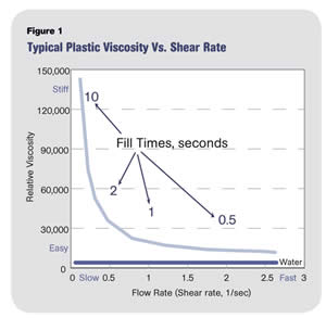
For a partial explanation, let us take a look at the material, particularly the shear sensitivity of all resins. Figure 1 represents a typical curve plotting viscosity vs. shear rate on linear axes instead of the typical log-log scales. Fill times are included to provide information on injection rates. Short fill times mean high shear rates and long fill times mean low shear rates. Nearly all plastics show this relationship of changing viscosity in response to shear rate. The resin is significantly stiffer at long fill times with low shear rates and flows significantly easier at short fill times with high shear rates. The viscosity difference between the two is huge. What has this have to do with our non-uniform multicavity parts?
Let’s look at our two cavities during filling and packing, with this viscosity curve data to help us “see” from the plastic’s perspective. During filling of each cavity, the shear rate is high, viscosity is low (easy flowing), and all is fine. However, if we freeze-frame the situation at the instant of switchover from first to second stage (packing), we see cavity “A” is full and cavity “B” is short. (For the sake of this article, we’re ignoring the many possible reasons why.) What is the viscosity of the plastic in cavity “A”? There is little if any flow, shear rate is extremely low, and viscosity is off the top of the graph, perhaps something like taffy. Cavity “B” is short, so plastic is still moving, shear rate is high, and viscosity is low, perhaps like cold molasses.
Now we switch to the second stage. Does the hold or packing pressure get delivered to each of the two cavities equally? Think of the viscosity difference and which viscosity will transfer or deliver the packing pressure to which cavity better. Cavity “B” has the advantage of the lower viscosity and will pack better. Cavity “A,” with taffy-like high viscosity, will be sinky, too stiff to pack. Perhaps Fig. 2 helps to explain the issue. We add more packing pressure and Cavity “B” flashes while Cavity “A” remains sinky.
Now what do we do? Many people start jacking up the clamp pressure or looking for a parting-line problem or other tool rework. But all these are a waste of time; nothing helps. By now the importance of delivering uniform flow to both cavities during the entire filling stage becomes clear. What are the chances of processing around this situation? None! You are fighting Mother Nature, the inherent law of physics that pressure will take the path of least resistance.
If this discussion makes sense to you, apply the thought process to molds where you have one or more blocked cavities. Again you are trying to violate a law of plastic flow, and it’s not nice to buck Mother Nature. The only answer is to find and fix the reasons for uneven filling in the first place—a lesson for another day.
About the Author
John Bozzelli is the founder of Injection Molding Solutions (Scientific Molding) in Midland, Mich., a provider of training and consulting services to injection molders, including LIMS, and other specialties. E-mail john@scientificmolding.com or visit scientificmolding.com.
Related Content

Are Your Sprue or Parts Sticking? Here Are Some Solutions
When a sprue or part sticks, the result of trying to unstick it is often more scratches or undercuts, making the problem worse and the fix more costly. Here’s how to set up a proper procedure for this sticky wicket.
Read More
Know Your Options in Injection Machine Nozzles
Improvements in nozzle design in recent years overcome some of the limitations of previous filter, mixing, and shut-off nozzles.
Read More
What to Do About Weak Weld Lines
Weld or knit lines are perhaps the most common and difficult injection molding defect to eliminate.
Read MoreRead Next

Understanding Melting in Single-Screw Extruders
You can better visualize the melting process by “flipping” the observation point so that the barrel appears to be turning clockwise around a stationary screw.
Read More
Lead the Conversation, Change the Conversation
Coverage of single-use plastics can be both misleading and demoralizing. Here are 10 tips for changing the perception of the plastics industry at your company and in your community.
Read More