TOOLING: How to Vent Mold Details
Principles to follow in venting bosses, ribs, pins, cores, slides, and lifters.
This month I will get into venting components and touch base at the end on parting-line bearing surface. Venting of mold components, actions, and part details at times is overlooked as a root cause of mold problems such as deposit buildup and erosion, as well as part-quality issues such as splay, burns, short shots, and inconsistent gloss. Many molders will try to process around these issues rather than modify the tool to address the problem.
With part details such as bosses and ribs, venting can be critical and can have a large impact on resolving maintenance and quality issues. Inserts or vents pins can be added to address these issues. At times, mold-flow software can predict where venting is needed, but in many cases modifications will need to be done after running the first shots.
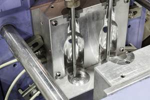
Screw bosses or similar details should already have venting designed in the mold. With vent pins, it is best to use an ejector pin or sleeves when possible to allow them to be more self-cleaning and accessible in the press to clean when in the forward position. One of the old standards for venting pins was to grind small flats on the side of the pin to the relief channel. I have found that this is not the most effective procedure. I prefer, based on many examples, to grind a ring vent or relief channel around the pin or sleeve with around 0.040- to 0.060-in. land and then grind the full diameter to the desired vent depth. This provides many times more area and volume for gases to escape, with no disadvantage (see image).
On bosses with sleeves and cores, I typically will grind a ring vent on both the sleeve and core pin to maximize venting. I have added venting many times over the years to ejector pins that were near the problem area. In most cases this is ineffective, because the pins are located on nominal wall stock and not in or at the end of the detail where the gas is trapped.
POROUS MOLD MATERIALS
When venting stationary inserts or core pins in rib or part details with venting issues, I recommend no more than 0.030- to 0.040-in. land and using maximum vent depths to get them as close to self-cleaning as possible. There are times when porous materials like Porcerax are used in problem or backfill areas. This can be a good option when normal venting methods do not work. But they require the mold shop to understand how to properly machine or EDM the part surface to prevent plugging the pores while providing vent channels or holes to reduce the area the gasses need to escape through. And you will have to understand proper cleaning methods for porous materials on the molding side. At times I feel porous materials can be over-used.
Some years back, we had a PC lens part with a rib detail where Porcerax was added to address a burning problem. We had daily issues with this insert getting plugged and requiring cleaning. I removed the insert, replaced it with a steel insert, cut a vent track 0.030 in. from the part detail, with the vent 0.002 in. deep. This provided exceptional venting and needed cleaning only with the 100,000-cycle PM (preventive-maintenance) frequency. I am not suggesting that porous materials such as Porcerax are not needed at times; I just recommend that you look at all the options.
Components such as slides and lifters do not always get enough attention with regard to venting. Typically these actions have details that create gas traps and knit lines that need to be vented. And in most cases, it is easy to add venting in the problem areas. With lifters, there would typically be a parting line in the detail where you can add a vent track and let the gases exit down the lifter shank to atmosphere. The same goes for slides, where you can add venting to the shut-offs so gases easily exit to atmosphere.
When details in cavities, slides, or lifters are in the solid, and no component is available to add venting, you still have options. If there is a shutoff, you can add a hole through it to atmosphere. You then lighten up the shutoff so it is open like a vent. In some cases I have EDM-ed holes as small as 0.030 in. when the shutoff detail was very small or the core had a small diameter. This option can be cheaper than adding an insert, ejector pin, or core, but is not always the best option.
AN UNUSUAL CASE
Last month I said I would mention a very rare case where we created a Venturi effect with venting, which contributed to a visual defect on the part. A screw boss detail in a lifter was trapping gas and causing splay on the part surface as the gas was pulled back into the plastic flow. We added a vent hole through the core detail in the lifter to atmosphere and vented the shutoff. This eliminated the splay issue. But after a couple of runs the defect came back, so I had one of my tool makers open the shutoff to where it was just starting to flash to make sure it was wide open and would vent efectively.
When the tool went back in the press, we could not get rid of the defect, which had me extremely puzzled. I took a look at the two-cavity tool and noticed one of the vent holes was filled completely with plastic. So we were having the defect on both cavities with one being wide open and one being plugged. We cleaned out the plugged vent hole but it was still not open to atmosphere. When we started back up, the defect was gone in the cavity on which we had cleaned the vent hole. After playing around, we found that by having the hole clean but not open to atmosphere we could get rid of the defect.
We concluded that the vent was too deep and was pulling air into the cavity. This backs up the theory that in some cases a blind pocket not open to atmosphere can provide venting. But these are rare situations. In most cases, it is prudent to have maximum vent depths and be open to atmosphere.
REMEMBER PARTING-LINE BEARING SURFACE
I just want to close with a little more on parting-line bearing surfaces. As I explained in a previous column, there is no disadvantage to a 100% parting-line bearing surface. Too little bearing surface contributes to many issues with vents closing off and parting burrs on cavity edges, and it can stress shutoffs as the tool coins in.
It really comes down to tonnage per square inch. I challenge you to calculate this some time. Just by going from 1 in.2 to 2 in.2 you have doubled your surface area and reduced tonnage/in.2 by half. Going from a 2 x 2 in. bearing pad to 4 x 4 in. increases your area fourfold. I know this is basic math, but I am amazed by how often this simple logic is overlooked. Many times I have witnessed where the intended bearing surface had been ground away by the tool maker spotting it. This is just a reminder to look at bearing surface when you are having an issue with vents getting coined shut—unfortunately, a very common issue.
Related Content
The Effects of Temperature
The polymers we work with follow the same principles as the body: the hotter the environment becomes, the less performance we can expect.
Read MoreSolve Four Common Problems in PET Stretch-Blow Molding
Here’s a quick guide to fixing four nettlesome problems in processing PET bottles.
Read MoreImprove The Cooling Performance Of Your Molds
Need to figure out your mold-cooling energy requirements for the various polymers you run? What about sizing cooling circuits so they provide adequate cooling capacity? Learn the tricks of the trade here.
Read MoreThe Importance of Melt & Mold Temperature
Molders should realize how significantly process conditions can influence the final properties of the part.
Read MoreRead Next
People 4.0 – How to Get Buy-In from Your Staff for Industry 4.0 Systems
Implementing a production monitoring system as the foundation of a ‘smart factory’ is about integrating people with new technology as much as it is about integrating machines and computers. Here are tips from a company that has gone through the process.
Read MoreProcessor Turns to AI to Help Keep Machines Humming
At captive processor McConkey, a new generation of artificial intelligence models, highlighted by ChatGPT, is helping it wade through the shortage of skilled labor and keep its production lines churning out good parts.
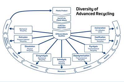
Read MoreAdvanced Recycling: Beyond Pyrolysis
Consumer-product brand owners increasingly see advanced chemical recycling as a necessary complement to mechanical recycling if they are to meet ambitious goals for a circular economy in the next decade. Dozens of technology providers are developing new technologies to overcome the limitations of existing pyrolysis methods and to commercialize various alternative approaches to chemical recycling of plastics.
Read More






.png;maxWidth=300;quality=90)
