- Home
- Conveying Equipment News
- System Types
- System Operation
- System Economics
- System Design
- Installation
- Components
- Controls
- FAQ

Basic Performance Characteristics of Pump Types
Maximum vs. Operating Vacuum
To get the maximum benefit from your conveying system, it’s important to understand what these terms mean and why they are important.
Maximum Vacuum (measured in inches of mercury) is the maximum safe pulling capacity of the pump. Vacuum relief devices are often included with a pump to prevent operating above this level, though operating at maximum vacuum on a continuous basis will lead to more frequent maintenance and reduced blower life due to elevated operating temperatures.
Operating Vacuum is the highest vacuum level a conveying system should pull during normal operation, and it’s the basis for calculating the system’s maximum conveying rate. Operating a conveying system at the specified operating vacuum, as opposed to the pump’s maximum vacuum, leaves “wiggle room” for unexpected changes, such as a dirty filter or varying material types, and leaves some extra vacuum in reserve to help clear an overfed conveying line of material slugs.
Free Vacuum is the vacuum that results from pulling air without material through the connected system tubing. The difference between Free Vacuum and Operating Vacuum represents the approximate vacuum energy available to move material when using PD and Claw type pumps. Regenerative pumps move much more air as vacuum levels decrease, so excessive air speeds create an artificially high Free Vacuum level with these pumps.
Basic Rules for Pump Selection:
Rule #1 - The pump must generate enough vacuum to overcome the resistance of the air and material as it moves through the length of tubing for the installed system.
Calculating the resistance of air and material in a conveying tube requires a complex set of equations and variables that are beyond the scope of this format. Key factors include velocity pressure, tube diameter and length, friction constants, and pellet characteristics.
Many equipment suppliers rely on rules of thumb relating “Equivalent Distance” conveyed to expected resin transfer rate. These rules are often derived from testing, so they’re reliable when evaluating applications that fall within the tested range.
“Equivalent Distance” is often confused with actual horizontal distance to be conveyed. Other factors add resistance as well, and must be included with horizontal distance to accurately estimate the resulting resin transfer rate. The typical factors associated with Equivalent Distance include:
| 1’ horizontal =1 equivalent ft. | 1’ vertical = 2 equivalent ft. |
| 1’ flex hose = 3 equivalent ft. | Each elbow = 20 equivalent ft. |
| 1’ vacuum line = 0.2 to 0.6 equivalent ft. (depends on diameter and distance) | |
| (vacuum line = tubing between the resin receiver and the vacuum pump). | |
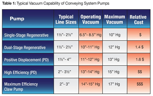
The key for this step is to understand the vacuum pulling capacity of the available pump technologies, and whether they meet or exceed the system requirements.
Rule #2 – The pump must create the appropriate air velocity at the material source to sweep resin into the tubing and carry it to the destination receiver.
The first consideration is creating the airflow and resulting velocity required to sweep resin into the tubing at the material source. This velocity is often called pickup velocity, or saltation velocity. There are a number of methods used to calculate this value, and they rely on material specific factors that are usually verified through testing. For commonly used plastics, the range is 3000 feet per minute (fpm) at the low end, and 4500 fpm on the extreme high end. Most plastics can be transferred using a pickup velocity between 3000 – 3500 fpm.
The second consideration is the material’s sensitivity to variations in air velocity. Some resins can break down as speed increases, and others can break down your system’s elbows and other impact points through erosive wear as speed increases.
The following chart compares the airflow versus vacuum for both Regen and PD pumps operating at constant speeds. Note that the Regen pump starts out at a higher speed than a PD pump due to its direct drive arrangement. This creates higher starting velocity. Also note the Regen pump airflow, and resulting velocity, increases more dramatically than PD pump airflow as the system vacuum requirements decrease.
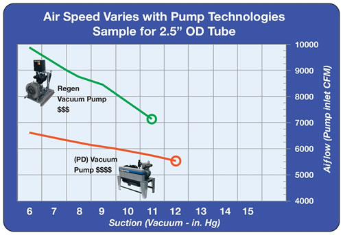
Result #1: Regen pumps move materials at higher speeds than PD pumps, which can lead to excessive material degradation or erosive wear on your system components. Examples of material degradation for sensitive materials include angel air, streamers, contaminating buildup or excessive dust, depending on material.
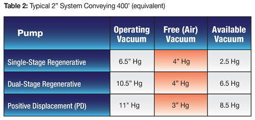
Result #2: Since velocity increases resistance to movement in a conveying system, Regen pumps use more of their operating vacuum just to pull air through a vacuum line (as compared to a PD pump), leaving LESS of their operating vacuum to pull material from source to destination. (See Tables 2-3 below)
These two results often lead to Regen pump suppliers adding velocity control devices into their systems. It’s important to understand the complete operating picture of a given pump technology before deciding which to use, and what optional features may be needed.
System Design
You probably would not try to design and build your own automobile and the same is true of vacuum conveying systems. Talk to a professional systems design specialist who represents a company with a full range of options for receivers, pumps, abrasion-resistant components and velocity control.
The system designer will ask a lot of questions about the types of materials you will be conveying, machine capacities and more. He will calculate the equivalent distances, the line sizes required and use pump curves to suggest the type of vacuum pump that best suits your current and expected future needs. It is always best to plan ahead for expansion.
Being able to choose from a full range of pumps is of can be a great benefit to maximizing a conveying system’s performance. The following 2 tables show how Free Vacuum, or the resistance to moving only air (without material) helps to estimate relative pump technology capability for a given installation. Higher Free Vacuum leaves less Available Vacuum to transport material.
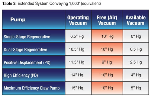
As distance increases, Free Vacuum can begin to overpower the pump’s Available Vacuum for moving material. Suppose you want to expand a system to include more machines, which also increases the Equivalent Distance for conveying to 1000 feet. Traditional Regen and PD pumps have limited Available Vacuum energy at this distance, so you’ll be faced with 2 choices:
- Increase system capacity with larger diameter conveying tubing. Unfortunately, this requires tearing out your existing pump(s), and all of your existing conveying lines.
- Investigate alternative higher vacuum pump technologies to replace the existing pump(s), but can still use the existing installed tubing.
Option 1 means you’ll rip-and-replace the existing system, and could incur excessive capital costs and suffer major interruptions to existing production, so the smart thing to consider is alternate pump technologies associated with Option 2.
In the table, we see when the system is lengthened to 1000 feet, the first three types of pumps have little or NO Available Vacuum for transporting material. At the same time, the pumps with higher operating vacuum capacities will be able to transport material. When this is the case, the wise choice is to replace the existing pumps with either a maximum efficiency PD pump, or a Claw pump. In almost all cases, the maximum efficiency PD pump is chosen because of the comparatively high cost of the claw pump technology.
Pump selection is key to your system’s effectiveness and efficiency. To reap the maximum benefits from your investment, work with a supplier who can offer a full range of pump technologies to ensure the proper solution for your conveying needs.