
Computer Flow Analysis Helps Develop New Profile Dies Faster
Computational fluid dy namics (CFD), or flow analysis, is routinely applied to dies for cast or blown film.


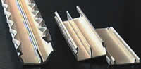
If resin exits the die too fast, it causes waves—seen here in the test profile at the far left.
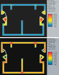
CFD images show polymer flow rates in a profile die: Red indicates highest speed, average speed is yellow, and slowest flow is blue. Uneven flow in the top example was balanced by using round restrictors to slow the melt in the fastest-flowing areas, as seen in the bottom image.
Computational fluid dy namics (CFD), or flow analysis, is routinely applied to dies for cast or blown film. OEM die makers usually have their own proprietary software programs, or they obtain them from universities or commercial vendors.
Profile dies, however, are still mainly designed by trial and error using methods that have changed little over the past 40 years. Virtually all profile extrusion companies design their own dies, relying on the experience of their die designers. Part of the reason is that profile dies are relatively inexpensive—they are usually made of aluminum plate and cost only around $3000 to $4000. But there’s a hidden cost because balancing each new die uses up production time and material.


More complex profile shapes make die balancing even slower and more difficult. That’s where flow analysis could bring a better understanding of what is happening, de-mystify the process, and speed up the trial-and-error development stage.
Don’t make waves
During development, many dies initially leave waves in the profile, as shown in the accompanying photo of the first trial run of a die for a cable tray and cover. The explanation of the waves is simple if you look at a CFD profile of the velocity of the polymer flowing out of the die (see top example, bottom right). It shows a severe speed imbalance in melt flow through the die.
The colors in the CFD output represent the speed of polymer just before it exits the die. Blue indicates slow, yellow is average, and red shows maximum velocity—which in this case is 260 mm/sec, or over four times the average rate of about 58 mm/sec. As the polymer leaves the die, it is drawn by a puller or haul-off at a speed generally a little faster than the average rate to maintain tension. So all those different melt-flow speeds must rearrange themselves so all the material moves at the same speed—referred to as plug flow.
Since the material can only move at the haul-off speed once it leaves the die, material flowing slower than this speed stretches as it exits, causing it to thin out. Material flowing faster jams up and swells. It is impossible for the material to swell to four times its initial size and maintain mass continuity, so the material buckles and makes waves.
One obvious solution is to increase haul-off speed until the waves disappear. The problem with that is that slower-moving material would then stretch even more. If it doesn’t actually tear, it will thin too much to achieve the required wall thickness. A better solution is for material that’s moving too fast to be slowed down or redistributed to other parts of the profile so there isn’t such a large variation in flow speed at the die exit.
The next problem is that there are many ways to achieve this redistribution. One can restrict the flow in the fast-moving area by making the channel smaller. Or one can make the channels in the slow-flow areas larger, so that more material chooses that path. Or one can add some type of flow restriction to the high-flow areas to slow them down.
How CFD can help
One of the main challenges of die design is to determine the channel size that will result in balanced restriction and flow. For a simple profile with all the walls of equal thickness, channels may be equal in size. But when profile wall thickness varies, flow balancing is much more difficult because the relationship between channel width and flow resistance isn’t linear.
The change in resistance caused by a change in channel width has a cubic relationship. For a Newtonian material, it is magnified to the third power. For polymers, which are non-Newtonian (shear-thinning), the effect can easily be magnified to the fifth power. This means that a channel that is only 15% larger than other channels in a profile may draw twice as much material flow. If the average channel width is 2 mm, a difference of only 0.3 mm can thus double material flow in that section.
CFD can simulate the different potential solutions to show which is best, saving the machine time and resin consumed by running actual trials. The bottom CFD image shows the optimum solution for the wave problem in this particular profile. Circular obstructions, or restrictors, are placed in the high-flow channels to restrict flow in these thicker areas by increasing wall surface area and consequent frictional drag on the melt. Now the maximum velocity (red) is significantly reduced to 117 mm/sec, only about twice the average velocity at the exit.
It’s virtually im possible to get the flow velocity to be identical everywhere within a die. Velocity is assumed to be zero (or at least very slow) near the die wall, so there will always be some variation. Maximum velocity in the channel is typically around 1.5 times the average velocity. A flow rate twice the average is high, but within acceptable limits. Now the desired profiles can be made without a ripple.


Related Content

Online X-Ray Inspection Boosts Extrusion Quality
Höhle uses Sikora’s x-ray measuring systems for inline quality control of extruded microducts.
Read More
Crosshead Die for Elastomers Adjusts Easily
NPE2024: Mechanically actuated gum space adjustment requires only ordinary socket wrench.
Read More
Wisconsin Firms Unite in Battle Against Covid
Teel Plastics opened new plant in record time, partnering with AEC & Aqua Poly Equipment Co. to expand production of swab sticks to fight pandemic.
Read More
How to Effectively Reduce Costs with Smart Auxiliaries Technology
As drying, blending and conveying technologies grow more sophisticated, they offer processors great opportunities to reduce cost through better energy efficiency, smaller equipment footprints, reduced scrap and quicker changeovers. Increased throughput and better utilization of primary processing equipment and manpower are the results.
Read MoreRead Next

Lead the Conversation, Change the Conversation
Coverage of single-use plastics can be both misleading and demoralizing. Here are 10 tips for changing the perception of the plastics industry at your company and in your community.
Read More
Processor Turns to AI to Help Keep Machines Humming
At captive processor McConkey, a new generation of artificial intelligence models, highlighted by ChatGPT, is helping it wade through the shortage of skilled labor and keep its production lines churning out good parts.
Read More