
Don’t Overlook Gate Location
Molders take heed: Gate location is the root cause of many molding difficulties. You’ll be doing yourself a big favor by spending some time and thought in determining the best gate location. Here’s what to look for.
Gate location affects orientation of polymer molecules and how the part will shrink. If a part is long and narrow and must be absolutely straight, then you need to gate it on the end. If a part must be absolutely round, gate it in the center
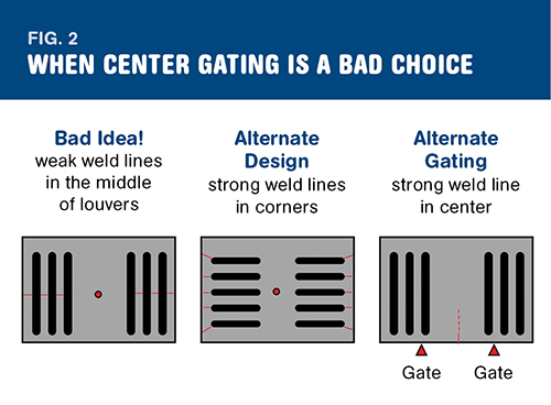
The designer of fan shroud wanted the louvers to be vertical and wanted to gate the part in the center so that the gate mark would be hidden by a company logo cemented on top. But this approach resulted in the formation of very weak weld lines in the middle of all the louvers, which would easily snap in half under impact. The solution is to either rotate the louvers 90° or, if the louver design can’t be modified, change to multiple gates along the edge of the part.
Gate location affects orientation of polymer molecules and how the part will shrink. If a part is long and narrow and must be absolutely straight, then you need to gate it on the end. If a part must be absolutely round, gate it in the center.


Gate location can make or break your part design. Yet most CAD designers give little thought as to where to put the gate, or injectionpoint, on the part they design. They simply leave that detail to the moldmaker.
This is a big mistake. Along with choosing the wrong gate size and type (hint: don’t use a 1-mm diam. subgate for a large, glass-filled nylon or polycarbonate part), a less than ideal gate location is the root cause of many molding difficulties. If you designed the part, you own the part, and you’ll be doing yourself a big favor by spending some time and thought in determining the best gate location for it. Where the weld lines are, where the sink marks or voids will be, and how the part warps—all of these are determined by where the molten plastic is injected into the part cavity.


WHEN ONE IS BETTER THAN TWO
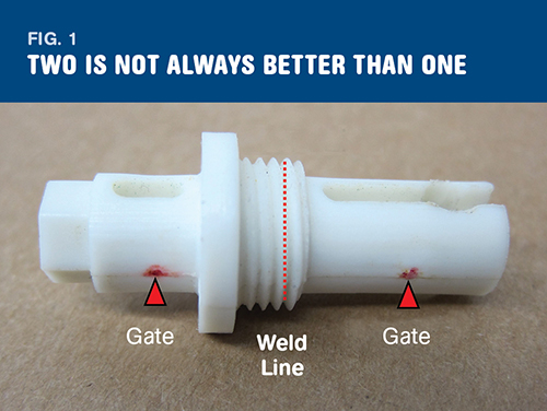
Take a look at Fig. 1. The designer who did this metal-to-plastic conversion thought he’d done everything right. He carefully chose the right material (20% glass-filled PBT). He did a computer finite-element analysis of his part design to make sure it could handle the required loads. And then he handed his CAD model off to the moldmaker.
The moldmaker—who is adept in machining tool steel, but knows very little about the flow of polymeric fluids—put two gates into this part. Only one gate was needed to fill this small part (about the size of your little finger), but if one gate is good, it stands to reason that two gates are better, right? Actually, no! Those two gates formed a weak weld line in the middle of this highly stressed part, resulting in its failure. Once those two gates were replaced with a single gate on the end, the part worked as designed.
My crude mock-up of a fan shroud design in Fig. 2 demonstrates the thought process you need to go through when determining gate location. The designer designed the louvers to be vertical, and wanted to gate the part in the center, hiding the gate mark with a company logo cemented on top. The problem with this scheme is the formation of very weak weld lines in the middle of all the louvers, which would easily snap in half under impact. The solution is to either rotate the louvers 90° or, if the louver design can’t be modified, change to multiple gates along the edge of the part.
An ideal injection molded plastic part should have a uniform nominal wall thickness; however, sometimes the end-use requires thick and thin areas.
If that is the case with your part, try to gate into the thickest area, and avoid gating into a thin area. Failure to do so can result in voids (many folks think they’re air bubbles, but they’re really shrink-induced voids) or sink marks. The best packing occurs at the gate, and you need the best packing you can get at a thick section to avoid these defects.
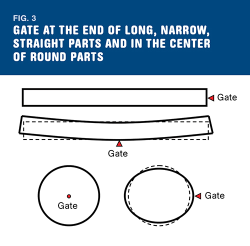
Gate location also affects the orientation of the polymer molecules and how the part will shrink. Figure 3 shows that if a part is long and narrow and needs to be absolutely straight, then you need to gate it on the end. (You’ll never see an injection molded plastic ruler gated on the side, because people won’t buy rulers that don’t have a straight edge.)
If a part is round and needs to be absolutely round, then you need to gate it in the center. Of course many part designs can handle 0.005 to 0.015 in. of bow or out-of-roundness, but if your part can’t, then choose your gate location wisely.
ABOUT THE AUTHOR
Joe Henz is a chemical engineer with 30 years of experience in the plastics industry, primarily with GE. He now teaches courses in injection molding and plastic part design at the Polymers Center of Excellence and UNC-Charlotte in Charlotte, N.C.. Email him at jhenz@polymer-center.org or visit www.polymers-center.org.


Related Content

Improve The Cooling Performance Of Your Molds
Need to figure out your mold-cooling energy requirements for the various polymers you run? What about sizing cooling circuits so they provide adequate cooling capacity? Learn the tricks of the trade here.
Read More
Understanding Strain-Rate Sensitivity In Polymers
Material behavior is fundamentally determined by the equivalence of time and temperature. But that principle tends to be lost on processors and designers. Here’s some guidance.
Read More
How to Get Rid of Bubbles in Injection Molding
First find out if they are the result of trapped gas or a vacuum void. Then follow these steps to get rid of them.
Read More
Solve Four Common Problems in PET Stretch-Blow Molding
Here’s a quick guide to fixing four nettlesome problems in processing PET bottles.
Read MoreRead Next

Advanced Recycling: Beyond Pyrolysis
Consumer-product brand owners increasingly see advanced chemical recycling as a necessary complement to mechanical recycling if they are to meet ambitious goals for a circular economy in the next decade. Dozens of technology providers are developing new technologies to overcome the limitations of existing pyrolysis methods and to commercialize various alternative approaches to chemical recycling of plastics.
Read More
People 4.0 – How to Get Buy-In from Your Staff for Industry 4.0 Systems
Implementing a production monitoring system as the foundation of a ‘smart factory’ is about integrating people with new technology as much as it is about integrating machines and computers. Here are tips from a company that has gone through the process.
Read More
Why (and What) You Need to Dry
Other than polyolefins, almost every other polymer exhibits some level of polarity and therefore can absorb a certain amount of moisture from the atmosphere. Here’s a look at some of these materials, and what needs to be done to dry them.
Read More