
How to Manage Multiple Heads in Accumulator Blow Molding
Don’t believe the myth that you can’t successfully run an accumulator-head machine with more than one head.


Don’t believe the myth that you can’t successfully run an accumulator-head machine with more than one head. Running multiple heads is not only feasible, it offers many advantages if approached correctly.
The right microprocessor integrated with the proper control software is key to success with multi-head accumulator blow molding systems. Today’s offerings enable tremendous precision and calibration to ensure smooth, reliable operation.


Processing controls must be able to run all heads in a proportional closed-loop mode for refill and for the pushout or purge velocity. Tooling should also have proportional closed-loop control of its position and proportional control of its specific head’s pushout position.
AVOID HYDRAULIC SATURATION
After the control, the single largest issue with keeping all heads in complete synchronization is appropriate hydraulic pushout pressure. Pushout pressure must not go into saturation—meaning that the hydraulic pushout pressure reaches the maximum system pressure before the selected pushout velocity has been achieved. When pressure reaches this saturated state, the entire process becomes basically an open-loop system and you’ve lost control of the heads. If everything is designed correctly and run correctly, you may never run into this situation.
To better understand what happens during saturation, look at the relationship between the control and hydraulic systems and the accumulator head. During pushout the control will generate a signal to the hydraulic system to generate the pushout velocity that the operator has selected or profiled. Usually there is more than one pushout velocity for the cycle; on newer machines this is usually a profiled velocity. As the head runs through the cycle there is a pressure drop created in the head. Once this pressure drop becomes higher than the hydraulic system can overcome, the head is in saturation.
On a single-head machine, hydraulic saturation is still a condition to avoid because it will keep the head from reaching the set pushout velocity. However, this is not as important on a single head, since you are not trying to keep it in synchronization with other heads. Hydraulic saturation with a single head means a loss of closed-loop speed control, but the effects are much less damaging because the saturation level is repeated on every cycle.
Also, if a single-head machine is in hydraulic saturation, any pushout velocity changes the operator makes may have little or no effect on the pushout speed at the saturation point. Finally, if the head goes into saturation it may be (and usually is) for only part of the pushout stroke. It could go in and out of saturation as the pushout speed profile is running.
There are many causes of high pressure drop that can lead to saturation:
•Tooling: As it opens and closes, there is a varying pressure drop created across the tooling. As the tooling die gap is reduced to create a thinner parison, the pressure drop increases. As the tooling is opened the pressure drop decreases.
•Push-out velocity: As the pushout velocity increases it takes more hydraulic pressure to push material through the die opening. At some point the combination of excessive pushout velocity and narrow die gap creates too much pressure drop across the tooling.
•Material temperature: If the melt temperature is too low its viscosity is increased, thus increasing pressure drop.
•Material melt index: Stiffer materials with lower melt index cause a higher pressure drop.
When any of the above parameters exceed the operating envelope, the system will go into hydraulic saturation.
To overcome the normal operating increases and decreases in pressure drop, the control system will vary the signal to the hydraulic proportional valve to maintain the selected velocity. If this pressure drop becomes too great and hydraulic saturation results, the control will continue to try to overcome the situation by increasing the command signal to the pushout valve.
Since this valve controls only hydraulic flow and not system pressure, the increase in the command signal will have no effect on the actual pushout velocity. The proportional gain loop in the control will keep increasing its command signal to the valve until it reaches its maximum output while trying to maintain the selected pushout velocity. If for some reason the hydraulic system pressure is low, the head will go into saturation much sooner, as there is less hydraulic pressure available, and this will cause the command signal to reach the maximum value much sooner than it should.
If your machine doesn’t generate an alarm for this condition there are two easy ways to detect its occurrence. The first is to check the actual pushout pressure. If it is approaching or at the available pressure to the head, saturation is occurring. The second check is to look at the command signal to the pushout valve: If it is approaching or has reached the maximum available signal level, this indicates that the control is trying to overcome saturation.
RESOLVING HEAD SATURATION
Your first step is to confirm that the system or maximum head hydraulic pressure is set correctly to the manufacturer’s recommendations. Processors commonly consider simply increasing system pressure, but this is not recommended because the rest of the machine and its components are sized and calibrated for the manufacturer’s recommended maximum system pressure. Next, the molder might be tempted to find a material with a higher melt index, but the resin was probably selected for its ability to satisfy part requirements and therefore isn’t changeable.
So turn your attention to what can be changed. The first consideration is verifying the correct melt temperature. If you’re running on the edge of saturation, a small increase in melt temperature can go a long way to correcting the condition.
Next, the operator can gradually reduce the pushout velocity until the head comes out of saturation and head control is regained. If the resulting pushout velocity is too slow, the operator can change the tooling profile to increase the die opening, but this will increase the part weight—typically an undesirable outcome.
After considering machine settings, focus on the tooling. Look at the tooling angles and the length of the land at the tooling exit point, since both of these can be adjusted to reduce the pressure drop. It is best to consult with a tooling design engineer on this, as tooling performance will be altered as the geometry changes.
The second consideration is the tooling diameter. If the tooling diameter is reduced, the resulting die opening will have to be increased to maintain a given part weight, resulting in a lower pressure drop. However, this method will most likely require using additional pre-blow to correct for the smaller parison diameter.
When running multiple heads, the pushout times must be synchronized exactly for consistent part quality. This is easy to control when multiple heads are running identical parts. However, when the heads are running different parts with different shot sizes, pushout time will be determined by the longest or thinnest parison. Normally you would make the longest parison the master head, and all other heads would follow its lead. The only reason the head with the longest parison would not be the master would be if one of the parisons was very thin and had to run a slow pushout velocity due to the pressure drop. Then you would make that head the master.
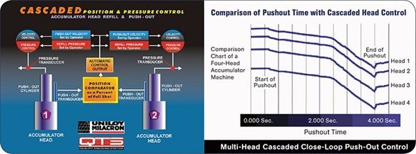
At Uniloy, we manage this with Cascaded Head Control technology, which matches the pushout times (not pushout speeds) on all heads to the selected master head, so all pushout times will be the same no matter what the shot size or parison length. You set the master head’s pushout velocity and the control system handles the rest. This is done to ensure you don’t wind up with a parison just hanging there, sagging while waiting for the others to catch up. With cascaded head control, the clamp-close command can be set to start at the precise moment to capture all parisons at the end of pushout.
If your control does not have this capability you can still manage pushout of different parisons, but it has to be done manually by adjusting the pushout speeds of each head individually so all parisons end simultaneously. This can be difficult to maintain as material blends change.
Another issue is refill synchronization. A multi-head process can’t work properly if the heads are not refilled evenly. This requires proportional-control synchronization between all heads, which is accomplished by metering the oil being pushed out of the head cylinder during refill. This process must be independent for all heads and under closed-loop control for all heads. It can’t be done with blocking valves, which create too much stair-stepping on the refill. By metering the oil out of all heads they will reach the selected shot size at the same time—this is important for the next parison pushout to be correct.
A properly set-up and maintained multi-head accumulator machine can produce consistently high-quality parts—even when they’re different sizes. By considering machine control, head saturation, and refill synchronization you can ensure the best performance from your machine system.


Related Content

Avoid Four Common Traps In Granulation
Today, more than ever, granulation is an important step in the total production process. Our expert explains a few of the many common traps to avoid when thinking about granulators
Read More
Use Interactive Production Scheduling to Improve Your Plant's Efficiencies
When evaluating ERP solutions, consider the power of interactive production scheduling to effectively plan and allocate primary and secondary equipment, materials and resources on the overall production capacity of the business and conclude that this is a key area that cannot be overlooked.
Read More
Mold Opaque White PET Bottles – Without Pigment
Trexel and Husky are cooperating on molding recyclable opaque white preforms for PET bottles, which provide a light barrier using foam instead of pigment.
Read More
50 Years...600 Issues...and Still Counting
Matt Naitove marks his first half-century in plastics reporting, with a few of his favorite headlines.
Read MoreRead Next

Processor Turns to AI to Help Keep Machines Humming
At captive processor McConkey, a new generation of artificial intelligence models, highlighted by ChatGPT, is helping it wade through the shortage of skilled labor and keep its production lines churning out good parts.
Read More
Understanding Melting in Single-Screw Extruders
You can better visualize the melting process by “flipping” the observation point so that the barrel appears to be turning clockwise around a stationary screw.
Read More
How Polymer Melts in Single-Screw Extruders
Understanding how polymer melts in a single-screw extruder could help you optimize your screw design to eliminate defect-causing solid polymer fragments.
Read More