
Reduce Hot-Runner Downtime With Proper Troubleshooting
Solve your problem faster by adopting a systematic approach. Here’s how to get going.
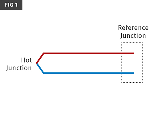
Simplified diagram of a thermocouple. Two wires of dissimilar metals are joined at the thermocouple tip to create the “hot junction,” and the wires are joined at the other end within the temperature controller at the “reference junction.” A difference in temperature between the two junctions causes a small current whose magnitude is related to the temperature difference.
One of the most common causes of overshooting hot-runner zones is pinched thermocouple wires. This creates a secondary junction, and the voltage output to the controller will be an average of that junction and the hot junction. The pinch point is typically against cold steel, so a false low-temperature reading will result, causing the controller to increase heater output and cause a zone temperature overshoot.
A zone with a pinched thermocouple will not show a temperature override—even though it is occurring—but it can conduct enough heat to adjacent zones to cause them to override too, though the result will be apparent on control readout.
Another issue is when one zone is overshooting while another is lagging behind. This is typically caused when the thermocouples and heaters of two zones have been swapped so that the thermocouple of one zone is controlling the heater of the other and vice versa. This is a case of crossed thermocouples.


When a mold is not running properly due to a hot-runner issue, the cost impact can be greatly reduced by fixing it right the first time. Too often, false assumptions are made about the cause of the problem and how to go about fixing it. This can cause unnecessary and costly cycles of removing the tool from the press, disassembling it, repairing it , reassembling it, installing the tool back in the press, and resampling it. This cycle can cost thousands of dollars, depending on the size and complexity of the tool. It’s important to approach troubleshooting systematically. Spending a little extra time up front can save a lot of time and money later.
The first step is to define the problem properly and gather as much information as possible. When a problem is identified while the mold is in the press, do some troubleshooting before removing the tool from the press. Too often the tool is removed with the assumption that the tool room can figure out the problem later. As a result a great opportunity is missed to gain more information quickly while the tool is still in the press. Although this is the case with any type of hot-runner problem, this article will focus on temperature-control issues.


TEMPERATURE CONTROL THEORY
Temperature control of a hot-runner system is a dynamic process. Heat is added to the hot runner in a few different ways. There are electrical heaters that are powered by a separate
temperature-control unit. Heat is also added by the molten plastic being injected through the hot runner on every cycle. This heat comes from the plastic itself as well as frictional heating created by the flow of the viscous polymer. At the same time, the hot runner is constantly radiating heat to the air pocket around it and losing heat through conduction at the tip, supports, and any other contact point with the tool.
When troubleshooting a temperature-control problem caused by an electrical issue, you must first understand how the temperature controller works. Almost all modern hot-runner systems use thermocouples to measure temperature. Thermocouples are very different from RTD probes, for which they are often mistaken. The resistance of an RTD probe changes with temperature, so a simple way of troubleshooting them is to check their resistance at a known temperature or to see if one has a resistance significantly different than all the others.
Thermocouples, on the other hand, have a completely different theory of operation. They work on a thermoelectric principle called the Seebeck Effect. A thermocouple is a made from wires of two dissimilar metals, joined at the tip of the thermocouple, creating what is known as the hot junction. The other end of the thermocouple is joined within the temperature controller; this is referred to as the reference junction (Fig. 1). When the hot junction is at a temperature different from the reference junction, a small current is created, and the magnitude of this current can be used to calculate the temperature difference between the two junctions.
Thermocouples are commonly cut to length to keep wiring neat. The resistance of a thermocouple is primarily dependent on its length. So unlike an RTD probe, the resistance of a thermocouple cannot be used as a definitive test to determine whether a thermocouple is good or bad.
Temperature controllers use different algorithms to determine how much power to apply based on the input from the thermocouples. But in simple terms, the controller sends power to the heaters until the thermocouple outputs reach setpoint. The temperature reading that the controller displays for each zone is based solely on the response it is currently seeing from the thermocouple. Although these two statements may appear obvious, keeping these simple facts in mind can help when troubleshooting temperature-control issues.
OVERSHOOTING SETPOINTS
Overshooting zones are one of the most commonly misdiagnosed types of problems, because the root cause is not always clear. Too often the wrong components are replaced blindly in hopes of solving the issue. For the reasons discussed above, an overshooting setpoint is never the result of a bad heating element.
Thermocouples are the more common culprit, but you need to gather more information to determine if a thermocouple is indeed the problem and if so, which one needs to be replaced.
If a hot-runner zone is discovered to be overshooting while the mold is running, the first step should be to take a minute and observe all the zones on the controller. Are any other zones
overshooting? Are any zones lagging below setpoint? Is the problem zone holding steady a certain level above setpoint, is it still rising, or is it oscillating? Next, stop the cycle for a few
minutes to see if the overshooting zone begins to stabilize or if it remains on its current pattern. The answers to these questions will help you zero in on the root cause, allowing you to quickly
and properly identify and repair the problem.
If the issue goes away when the cycle is stopped, most likely this is not an electrical issue. If the plastic being injected into the hot runner is significantly hotter than the manifold setpoint, or if the amount of flow through a section of the hot runner is creating excessive shear heat, then simple process adjustments will often resolve the issue. If they don’t, contact your hot-runner supplier but don’t waste time and money replacing working electrical components.
It’s important to understand how thermocouples react to damage. When one of the wires is cut the thermocouple circuit is broken. This typically will generate an “open thermocouple” alarm on the controller and can be diagnosed easily with a continuity check of the thermocouple zone. The more common failure of a thermocouple is a pinch. Thermocouple wires can easily become pinched if they are trapped between mold plates or part of the hot runner and a mold plate during assembly.
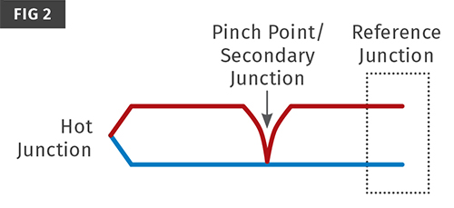
When thermocouple wires are pinched, the two wires can touch but not break and typically will not cause an alarm on the controller. When this happens, a secondary thermocouple
junction is created (Fig. 2) and the voltage output to the controller will be an average of that created at the hot junction and that at the pinch point. The pinch point is often against cold steel, so the thermocouple will output a low reading, causing the controller to send power to the heaters until the average of the hot junction and pinch point reaches setpoint, driving the true temperature at the hot junction well over setpoint.
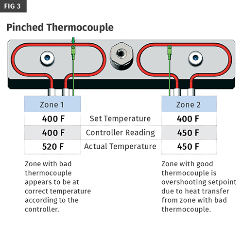
When this happens, the zone with the pinched thermocouple will not show a temperature
over setpoint but can conduct enough heat into an adjacent zone to cause that zone to override setpoint (Fig. 3). This is very easy to diagnose by reducing the temperature of the zones next to the overshooting zones to see if the overshooting zone begins to come down. If it does, you’ve identified the problem zone and should replace that thermocouple, not the thermocouple from the overriding zone.
Keep in mind that the adjacent zones on the hot runner many not be the adjacent zones on the controller. You need to refer to the hot-runner electrical zone schematic to determine the physical locations of the zones.
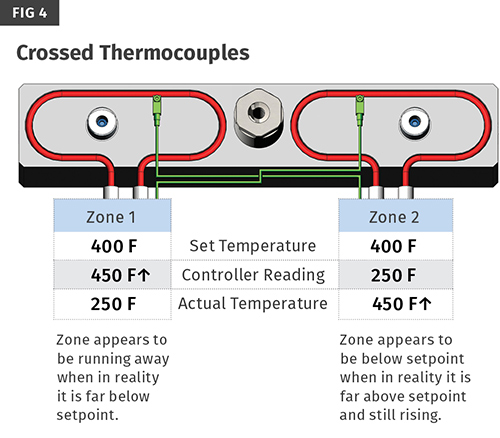
Another variation of an overshooting zone issue is when one zone is overshooting while another zone is lagging behind. This is typically caused when the thermocouples and heaters of two zones have been swapped so that the thermocouple of one zone is controlling the heater of the other and vice versa. This is a case of “crossed thermocouples” (Fig. 4). The thermocouple from zone 1 tells the controller to send power, but it’s sent to the heater for zone 2, causing zone 2 to continue to rise while the zone 2 thermocouple tells the controller to shut off power to zone 1.
This is usually the result of a wiring mistake in the hot runner itself. However, it can also be caused by bad cables or a setup on some controllers that allows you to effectively rewire a system from the controller itself by designating which thermocouple is paired to which heater.
Sometimes a wiring issue in a hot runner will be corrected by “temporarily” rewiring a cable because it’s easier to get to. If the wiring is not changed back it can cause the same problem the next time the cable is used with a different tool that does not have a wiring problem.
STRUGGLING ZONES
Zones not reaching setpoint can be a result of a failed heater, bad thermocouple, a cable/connector issue, or a heat-sink situation within the tool. These issues can be easier to
troubleshoot, but a proper methodology is still important. It’s usually best to check the easiest things first. Power down the controller and disconnect both ends of the cables. Inspect the connector pins for any that are bent or have pushed into the connector, breaking the electrical circuit.
Next, use a multimeter to check for continuity of the heater zones. Start at the cable connector for the controller and work your way towards the tool. If all heater zones show continuity then check the resistance of each zone and compare it to the value shown on your hot-runner
drawings. In many cases, a hot-runner zone can be made up of two heaters wired in parallel. If this is the case and one heater has failed, then the resistance of that zone will measure double the normal value. If a heater zone is found to be open or at double resistance, check the wiring inside the junction box before disassembling the tool.
Once the top plate is removed, do a visual inspection. Is there any plastic leakage or signs of a water leak that could be causing the problem? Although plastic is generally considered an insulator, it is much more conductive than air, so an isolating gap filled with plastic can prevent
a hot-runner zone from reaching setpoint.
If no obvious causes are apparent, then heat the hot runner to a safe temperature. Normal operating temperature is ideal, but if the hot runner is full of a plastic that may degrade you should heat it to a slightly lower temperature. Once the heats have stabilized, confirm the actual temperature next to each thermocouple on the hot runner with a calibrated hand-held temperature probe. Your calibrated temperature probe measurement should be within a few
degrees of that outputted by the thermocouple. If it is not, check for proper seating of the thermocouple. If that doesn’t solve the problem, replace the thermocouple.
Develop a good troubleshooting methodology and learn about the operation of the control system to quickly get to the root cause of hot-runner temperature-control problems.
You’ll find that gathering information while the tool is in the press is time well spent.


Related Content

Know Your Options in Injection Machine Nozzles
Improvements in nozzle design in recent years overcome some of the limitations of previous filter, mixing, and shut-off nozzles.
Read More
How to Optimize Pack & Hold Times for Hot-Runner & Valve-Gated Molds
Applying a scientific method to what is typically a trial-and-error process. Part 2 of 2.
Read More
How to Select the Right Tool Steel for Mold Cavities
With cavity steel or alloy selection there are many variables that can dictate the best option.
Read More
How to Get Rid of Bubbles in Injection Molding
First find out if they are the result of trapped gas or a vacuum void. Then follow these steps to get rid of them.
Read MoreRead Next

Understanding Melting in Single-Screw Extruders
You can better visualize the melting process by “flipping” the observation point so that the barrel appears to be turning clockwise around a stationary screw.
Read More
Processor Turns to AI to Help Keep Machines Humming
At captive processor McConkey, a new generation of artificial intelligence models, highlighted by ChatGPT, is helping it wade through the shortage of skilled labor and keep its production lines churning out good parts.
Read More
People 4.0 – How to Get Buy-In from Your Staff for Industry 4.0 Systems
Implementing a production monitoring system as the foundation of a ‘smart factory’ is about integrating people with new technology as much as it is about integrating machines and computers. Here are tips from a company that has gone through the process.
Read More