Use Your Gauge to Solve Processing Issues Upstream
Gauging systems have an often-overlooked but equally important role beyond measuring web thickness: They can be used as a diagnostic tool to troubleshoot the process. Here's how.
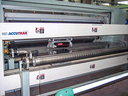
Shown here is a typical on-line gauging system thickness scanner on a cast PP line.
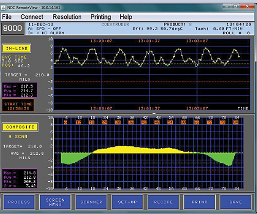
In this screen capture, the gauge is showing cyclical variation in a 214-mil sheet with a peak-to-trough variation of more than 5 mils. From the chart’s 2-min time span, we see cyclical variation occurring at 6.5 cycles/min. At a line speed of 8.6 ft/min, this equates to 5-mil variation every 1.3 ft. However, there appears to be more than one beat frequency occurring, so FFT analysis may be needed.
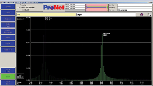
This FFT output reveals that this process has two dominant sources of cyclical STMD variations—one every 0.90 sec (4.7 ft of product), contributing 0.74 mils of variation; and a second every 0.40 sec (2.09 ft), contributing approximately 0.56 mils of variation.
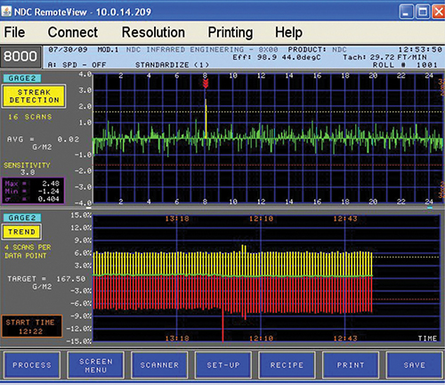
Streak-detection software can isolate recurring streaks even in noisy profiles like the one above. In this case, the software has found and marked a thick streak in lane eight of the profile.


On-line gauging equipment is an integral part of most film and sheet extrusion processes today. Virtually every biaxially oriented and cast film line in the industry is now equipped with some type of scanning on-line gauging system to measure and, usually, control the cross-web thickness variations and regulate average thickness. Many sheet and blown film lines also employ some type of on-line gauge to measure and regulate thickness.
Typically, these gauging systems are used by the machine operator as a tool to ensure that the product is being made to specification. While this is an extremely effective way to save raw material, reduce scrap, and optimize energy and manpower usage, the gauging system also has an often-overlooked but equally important role: It can be used as a diagnostic tool to troubleshoot the process.


NOT ‘BY-THE-BOOK’ SPC
Today, many manufacturers use tools like Statistical Process Control (SPC) to control their product and manage quality. But SPC was designed for typical “batch” or “stream” processes. In a batch process, one or several samples are grabbed from the batch, measured, and the data are used to determine the overall quality of the batch. Similarly, in a stream process, a sample is taken from the stream at a specified frequency, analyzed, and charted to define whether the product conforms to specification. SPC can provide effective control for these relatively simple processes.
The process is significantly more complex in film and sheet. Some have suggested that the best way to look at a web extrusion process is to think of it as having many “lanes” or an array of process “streams.” In reality, extrusion processors have to worry about product variation occurring simultaneously in two dimensions—across the width of the web, as well as down its length. Processors can control slow changes in product thickness along the length of the web by adjusting line speed or screw speed. But high-speed thickness fluctuations occur too quickly for any gauging system or operator to effectively control or remove.
If these sources of high-frequency variation cannot be controlled, you need to try to understand the sources of these variations to eliminate them and improve product quality.
The product of an extrusion process comprises three types of variation:
1. Profile variations (PRO): Thickness variations across the web, also called cross-machine or CD variations.
2. Short-term machine-direction variations (STMD): Cyclical or random thickness variations that occur at high frequency, usually in a time period of 1 min or less.
3. Long-term machine-direction variations (LTMD): Cyclical or random thickness variations occurring over a time period from several minutes to hours or even days.
Causes of PRO variations include an improperly adjusted die lip or restrictor bar, a temperature gradient across the die face, or a die improperly designed for the material being extruded. In blown film processes, profile variation can also be caused by a temperature gradient around the bubble circumference. A special case of profile variations is streaks, which are narrow but sharp gauge differences caused either by a buildup of carbon in the die lip (thin streak) or a gouge or nick in the die face (thick streak).
Causes of STMD variations include melt-draw resonance due to polymer/die setup mismatch, pulsating flow (screw surge) from an extruder due to a design problem or improper setup, and high-speed cyclical variations imparted in the haul-off due to roll run-out, bad bearings/ journals, or speed /drive regulation issues. With the possible exception of melt-draw resonance, these causes of high-speed variation usually have a defined frequency associated with them.
Causes of LTMD variations include extruder or die temperature oscillations due to a mistuned controller or improperly installed heaters or thermocouples; material formulation changes, including regrind or “fluff” ratios; screen-pack pressure buildup due to dirt accumulation; operator machine adjustments, particularly from shift to shift; inconsistent resin feed systems; and, especially with blown film, atmospheric changes due to ambient temperature, humidity, and barometric pressure.
In day-to-day usage by the machine operator, the gauging system can control most, if not all, profile (except streaks) and LTMD gauge variations. What the gauging system and operator cannot control directly are the high-speed STMD variations and the profile streaks. However, if we can define and isolate these two sources of gauge variation, we can take corrective action on the process to minimize or eliminate them.
HOW THE GAUGE CAN HELP
How can you isolate and define the sources of STMD variations and profile streaks? STMD variations can be isolated and visualized by a gauging system feature called “in-line” or “single-point” mode. In this mode, the scanning sensor is temporarily stopped at a defined spot on the web, and data is collected for a specified time period (typically 1 or 2 min). Collect STMD variation data at three positions (left, center, and right) across the web. Why? Because some forms of STMD variations may only affect a certain portion or side of the web (such as a bad bearing on one side of a cooling-roll stack).
Observing the STMD cycle(s) can often pinpoint a source of the variation—the periodicity of the cycle can usually be correlated with a process parameter. For example, if it is determined that a predominant component of STMD variation occurs 61 times/min, and the main extruder is operating at 61 rpm, then you can reasonably assume that the extruder is a cause of the STMD variation.
The gauging system can tell you the magnitude of the problem (amplitude of thickness cycle) and the source (by correlating the frequency with the operating rate of processing equipment), but it can’t tell you the actual cause—you need to determine that for yourself.
If the process is more complicated (such as a coextrusion line with multiple extruders), the STMD variation may consist of thickness variations from multiple sources, each having its own period and amplitude, all comingled into a complex in-line display readout. This may make it difficult to ascertain with the naked eye which device(s) in the process is/are the source(s) of the variability. This is where a Fast Fourier Transform (FFT) tool can be of great help. FFT is a mathematical tool that transforms the data collected in a time domain and converts it to a frequency domain. FFT will tell you which cyclical sources of variations are causing the greatest contribution of variation (amplitude) and at what frequency they are occurring.
Most gauging systems have an FFT tool available, either as a standard or optional feature. If your gauging system does not have an FFT capability, fret not—FFT utilities are available as PC applications and even as a part of the Microsoft Excel add-on Analysis Tool Pack. To use an external FFT program, you will need to work with your gauging supplier to determine how to extract in-line data out of your gauging system and onto a PC.
We won’t get into how to use Excel to yield an FFT here, but one word of advice: Some FFT programs won’t work at all or will only work marginally unless the size of the data array entered into them is an exact power of two (this simplifies the math that the FFT performs). This is why many gauging system profiles or in-line displays contain profile buckets that are 512 or 1024 data points in size.
Once you’ve determined the predominant source(s) of STMD variation, you need to put on your process engineer’s hat to determine its actual cause. If you find yourself at a point where you can’t determine on your own what is causing the variation, you have several options, including bringing in your machinery supplier to consult, or contacting a professional extrusion consultant. These individuals can be found through an internet search or by contacting trade associations or colleges/universities specializing in plastics education.
This sounds like a lot of trouble, but when you consider that this high thickness variability may be causing quality problems, producing additional scrap, and making the process less controllable, the cost of consulting will be paid back many times over by eliminating these issues.
ADDRESSING STREAKS
Profile streaks are the other issue that may need to be addressed. Detecting them is not always easy. First, the gauging sensor must have the resolution to detect these streaks, and it must be able to do so at full scanning speed. Second, the gauging system must be able to filter out other sources of variation (such as gauge noise or STMD thickness variation) so that these narrow streaks can be detected reliably. Some gauging systems have software features dedicated to the task of performing specialized analysis to detect streaks. These utilities employ special mathematical models that look for repetitive, narrow patterns that continue to occur in spite of process noise.
Once you detect the streak, you can take action. If the streak is caused by dirt or carbon buildup, the operator may be able to clean the die lip with a brass cleaning tool, with minimum disruption to the process and product. If this is not possible, you will need to consider how big and how many streaks you can tolerate before you shut down for a die cleaning. If the streak is due to permanent damage to the die face, you will need to contact the die maker to determine the cost and logistics to refinish the die.
CONTROL … AND DIAGNOSE
An on-line gauging system goes beyond day-to-day control. It is a powerful device that provides benefits whether it is performing a normal process-control function or is used as a diagnostic tool. In either use, economic benefits accrue in both time and money. Learn to use the full capabilities; it can only improve your overall process performance.
ABOUT THE AUTHOR
Hector Marchand has been v.p. of marketing for NDC Infrared Engineering, Irwindale, Calif., since January 2000, and has spent most of the last 35 years in the industrial on-line gauging business. In the late 1980s, he served as U.S. product manager for Reifenhauser’s blown film product line. Early in his career, he worked as a process engineer at American Can Co.’s flexible packaging facility in Neenah, Wis. (now part of Bemis Co.). Contact: (626) 939-3897; email: hmarchand@ndc.com; web: ndc.com.
Related Content

How to Extrusion Blow Mold PHA/PLA Blends
You need to pay attention to the inherent characteristics of biopolymers PHA/PLA materials when setting process parameters to realize better and more consistent outcomes.
Read More
Wisconsin Firms Unite in Battle Against Covid
Teel Plastics opened new plant in record time, partnering with AEC & Aqua Poly Equipment Co. to expand production of swab sticks to fight pandemic.
Read More
ABC Technologies to Acquire Windsor Mold Group Technologies
The Tier One automotive supplier with compounding and blowmolding machine capabilities adds the 50-yr-old molder and moldmaker.
Read More
Solve Four Common Problems in PET Stretch-Blow Molding
Here’s a quick guide to fixing four nettlesome problems in processing PET bottles.
Read MoreRead Next

Troubleshooting Screw and Barrel Wear in Extrusion
Extruder screws and barrels will wear over time. If you are seeing a reduction in specific rate and higher discharge temperatures, wear is the likely culprit.
Read More
Advanced Recycling: Beyond Pyrolysis
Consumer-product brand owners increasingly see advanced chemical recycling as a necessary complement to mechanical recycling if they are to meet ambitious goals for a circular economy in the next decade. Dozens of technology providers are developing new technologies to overcome the limitations of existing pyrolysis methods and to commercialize various alternative approaches to chemical recycling of plastics.
Read More
Why (and What) You Need to Dry
Other than polyolefins, almost every other polymer exhibits some level of polarity and therefore can absorb a certain amount of moisture from the atmosphere. Here’s a look at some of these materials, and what needs to be done to dry them.
Read More