
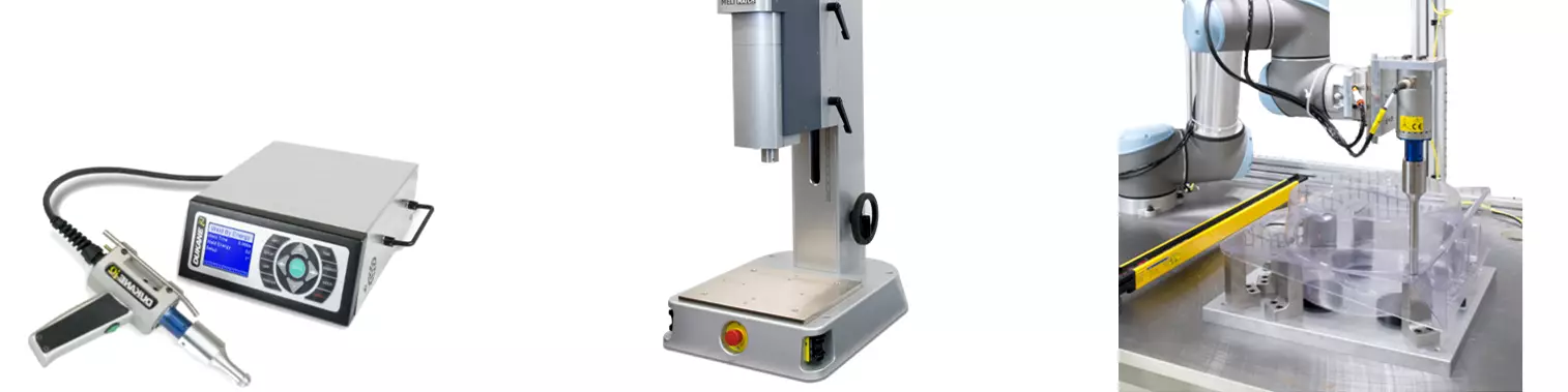


FIG 1 Typical ultrasonic welding equipment (l-r): a hand probe, a standard press system, and a probe system on a robot. (Images: Dukane)
Imagine for a moment that you are assigned to an ultrasonic welding project. You have two plastic parts that must be joined, and ultrasonic welding is the technology of choice. You walk up to your fully configured welder and stare blankly at a screen, the software littered with options for controlling the weld process. You have no idea what any of these buttons do. Deep down, you know this machine is capable of giving you the perfect parts you need every time. But you have no idea where to start, or what to select to get there. What do you do?
Benefits of Ultrasonic Welding


Types of Ultrasonic Welding Systems and How to Choose
Before you can consider what controls to bring to bear on your welding project, you must first understand how the technology works. Fundamentally, ultrasonic welding is a process by which reciprocating, high-frequency vibrations are used to bond two plastic parts together. These vibrations are typically above the range of human hearing — 15, 20, 30, 35 and 40 kHz being common selections — which is why the method is referred to as ultrasonic welding. The amplitude of these vibrations is very small, usually between 5 to 125 μm, and is selected for the resin composition and overall size of a particular assembly.
To achieve a weld, you apply an ultrasonic vibration to two thermoplastic parts under compressive load. This generates friction at the interface, which creates a rapid buildup of heat. Within fractions of a second, the temperature is sufficient to melt the plastic at the interface. Once enough heat is generated, the resin of both parts melts and flows together, creating a chemical bond between the components. When the vibrations are terminated, the resin rapidly cools and solidifies. The two parts are now formed into a single assembly.
Related Reading: How to Solve Common Ultrasonic Welding Problems
Benefits of Ultrasonic Welding
The benefits of this technology are significant. It eliminates the need for glue or mechanical fasteners. No external source of heat is required. The process is fast, requires only electricity and (sometimes) compressed air as consumables, and is easy to scale to any level of manufacturing. Why, then, is welding often one of the most difficult parts of a project to dial in? The answer lies in how well you control your weld process.
Modern manufacturing environments require significantly more visibility of the welding process than ever before. Ultrasonic welding has been around for over 75 years, but the most impactful advances in controlling the process have come only in the last 30 years. For more than half the technology’s life, it was an open-loop process — the ultrasonics were either on or off. Modern welding systems offer significant improvements over this approach, with layered features allowing you to control each step of the welding process. When properly used, these controls result in extremely capable weld processes.
Which weld process is best for your specific assembly? The answer depends on what equipment is used, what weld joint your assembly employs, and what functional requirements matter most to you.
But how do you define “properly used”? How do you select which weld process is best for your specific assembly? The answer is driven by three fundamental decisions: what equipment is used, what weld joint your assembly employs, and what functional requirements matter most to you. Knowing these three things, you can select the process controls to ensure you achieve a reliable weld every time.
Related Reading: Can Plastic Recyclates be Welded Ultrasonically?
Types of Ultrasonic Systems and How to Choose
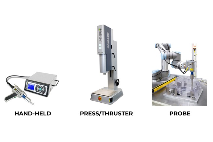
First, you must understand what your equipment can do. Welding equipment comes in various shapes, sizes and levels of complexity. For the sake of this discussion, we consider three large categories. In decreasing order of complexity, there are self-contained press systems, custom probe systems, and hand-held systems. Which system you have helps determine which process controls are available to you. Alternatively, knowing what your part must do helps determine which process controls you need, and consequently which equipment you should employ.
Servo welders offer the most control over your weld process.
Most suppliers of ultrasonic equipment offer self-contained press systems, which typically include the largest selection of advanced controls. These are usually benchtop-style thruster systems, traditionally actuated by pneumatic cylinders. Led by the iQ ES Servo Welder, introduced by Dukane 14 years ago, electric servo-based press systems have become increasingly popular. As manufacturers demand ever-tighter process control for their products, the capabilities of servo-driven welders become paramount. There are a variety of these systems in the market today, and their usage is steadily increasing. As we will see, servo welders offer the greatest control over your weld process of any equipment available today.
Probe-based ultrasonic welding systems are most common in custom automation. These tend to be large, automated machines that are purpose-built for a specific product or process. Given that each is unique, there is significant variation in capability. The controls vary from basic open-loop systems that have existed since the advent of the technology, to fully featured ones that approximate what press-based systems can do. Generally, though, they are less capable than press systems.
Lastly, a hand-held probe is an operator-actuated version of a probe system, used primarily for testing, repair work and small-batch manufacturing. It is not intended for precision manufacturing environments, as it offer the fewest control features of any ultrasonic system.
Starting the Weld Correctly: 5 Steps of the Ultrasonic Weld Process
Having a sense now for the general types of equipment available, we can discuss the various control options. The weld process is broken into five general steps, each with individual options for control.
- Fixturing — controls how the parts are presented to the horn (also known as a sonotrode).
- Trigger — controls how you initiate the weld.
- Weld method — controls how the melt propagates, and what variable is measured during the weld.
- Hold cycle — controls how the parts resolidify and cool.
- Analysis — collects and analyzes data from the weld, to confirm that your requirement was met and make any changes as necessary. Together, these five steps, and the sub-controls that regulate how each step is enacted, make up process control in ultrasonic welding.
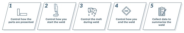
FIG 2 The five steps for ultrasonic welding process control.
Fixturing Plastic Parts for Ultrasonic Welding
Almost all ultrasonic welds require rigid fixturing of the plastic parts under the horn. The first step — controlling how the parts are presented — is accomplished via this fixturing. It ensures consistent alignment, leveling and support for the plastic, so that the incredibly precise controls to follow have maximum effect. The weld joint, or part interface geometry, requires direct support via the fixturing. In some cases, external clamping of parts is also required. Fixtures are typically made of steel, aluminum, acetal or poured urethane. Inadequate support, or too much compliance in the fixture material, will attenuate the ultrasonic vibration — a recipe for inconsistent weld quality.
The weld process is broken into five general steps, each with individual options for control.
If you do not source your fixture from an ultrasonic equipment supplier, you should consult with their engineering team to ensure your solution is appropriate for your assembly. Poor fixture design has wreaked havoc on many a welding project, creating problems long before any parts are molded or assembly attempted. Having the correct tooling solution is imperative to establishing a capable welding process.
How to Initiate the Weld: Trigger Method
With your tooling situation resolved, the first equipment decision you must make is how to initiate the weld. This is step two of the weld process, and it is referred to as the trigger or trigger method. Fundamentally, this does two things: It tells the equipment when to turn on the ultrasonic vibrations, and it begins measurement for whatever weld method you are using (more on that later). Most modern systems have four distinct options: pre-trigger, trigger by power, trigger by force or trigger by position.
Pre-trigger is the simplest form of weld initiation. As the name suggests, pre-trigger turns on the ultrasonics prior to part contact. This is how all early welding systems triggered, as they had only simple on/off controls for the horns. Hand-based welding systems still function this way — the sonics are on when the operator pulls the trigger, regardless of any other factor. Systems that use pre-trigger experience more aesthetic part marking than the other methods, as the sonics are usually running at full amplitude before part contact. This can melt or damage the contact surface, which is often undesirable.
That said, certain types of welding use the pre-trigger method even today — in spot welding (surface-to-surface) and staking operations, which are common on probe-based machines. It is also the common method for any continuous operations, such as food cutting, as well as in certain sealing or film/nonwoven bonding processes. Modern press systems still feature pre-trigger as an option, though it is rarely the appropriate choice for this type of equipment.
Trigger by power is the second of the weld initiation options. This method is a proxy for trigger by force when your equipment does not feature a load-cell as part of the thruster package. It is common in probe-based systems doing spot-welding or staking and has use in film/nonwoven applications. Functionally, the horn descends towards the part while running at a low amplitude — maybe 20% to 40% of its full value. Once the horn contacts the part, the power required to keep the horn operating at its resonant frequency increases dramatically. The equipment watches for this power spike, and when it reaches a user-programmed value, initiates the weld. Because there is a direct relationship between the force the horn experiences and the power required to keep it at resonance, adjusting the value for trigger by power adjusts the force between the horn and plastic part. While not as accurate as trigger by force, trigger by power is an upgrade over pre-trigger for probe systems.
The most common trigger method used today is trigger by force. This approach requires a load-cell in the equipment and is usually reserved for press systems. Functionally, the horn descends onto the part with the sonics off. Once the horn contacts the part, the force between the horn and assembly begins to build and is monitored by the equipment. Once that force reaches a user-programmed value, the sonics initiate and the weld begins. It is the preferred selection when welding two rigid plastic parts together using a purpose-molded joint design (energy director or shear joint).
Trigger by force has the major benefit of accurately and repeatably seating the parts together prior to welding, ensuring intimate contact between the interface surfaces. Initial contact is vital to achieving a good weld, so use of this trigger method is key to improving your weld consistency. When paired with the “sensing-start” feature of a servo welder, which slows the press down just above part contact, this method can result in very consistent pre-weld force engagement. A similar, though less precise, effect can be achieved on pneumatic presses using a hydraulic speed controller or comparable device.
The final trigger option is trigger by position. This is a feature of servo-welder systems, as well as more highly featured pneumatic presses that include a linear encoder. In this method, a user programs a discreet position above the part to initiate the sonics. Trigger by position is most useful when welding tiny or delicate parts, which cannot reliably trigger with force due to their size or construction. It also works well for nonwoven cut-and-seal applications, where the compressibility of one of the materials prevents reliable force readings. It is essentially a pre-trigger, but at a given spot instead of at the top of the welder’s stroke.
Choosing the correct trigger method is as much a function of the equipment you have as anything else. For systems with a load cell, force is typically the first and preferred method. For probe systems, power is increasingly replacing pre-trigger. Delicate parts or certain nonwoven applications on servo systems may benefit from trigger by position. If your primary welding equipment is a hand probe, you are out of luck.
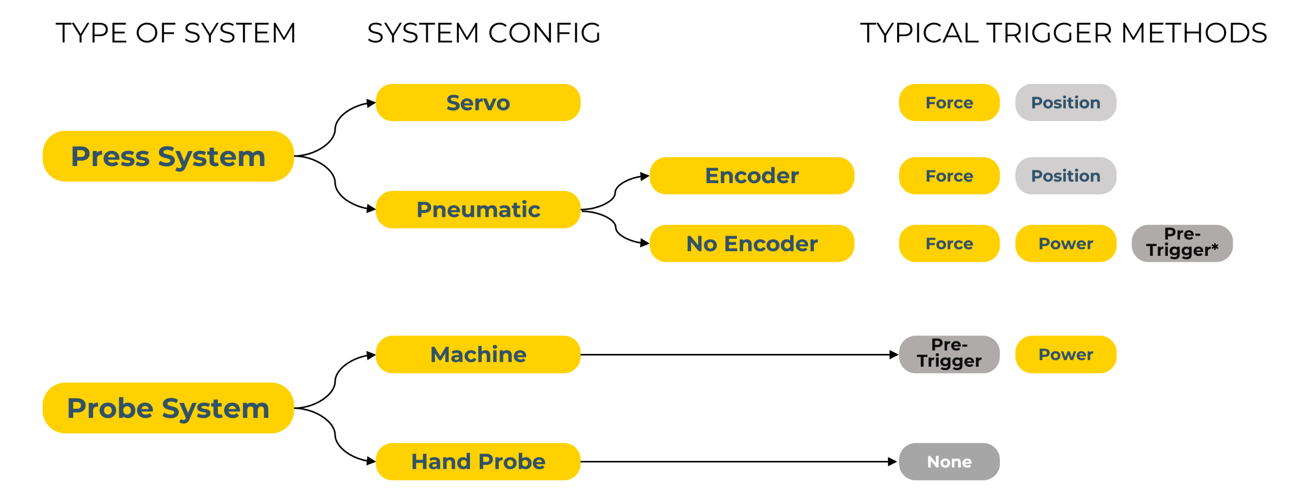
FIG 3 Typical trigger method selections by equipment configuration.
Selecting a Weld Method
With your equipment identified and trigger method selected, the next decision to make is selecting the weld method. It is a complex decision, one considering not only the equipment you have and the type of welding you are doing, but also the functional requirements of your part. Different methods lend themselves to different criteria, and there are often multiple solutions for any given product. Five basic options for weld method are common: time, energy, distance (or collapse distance), position (absolute distance), and peak power.
Weld by time is the most basic method and has been around since the advent of the technology. Sonics are engaged, and after a fixed duration, they are turned off. From the perspective of the weld, this is essentially an open-loop process. There is no feedback from the part on the energy used, distances traversed, or whether the parts were even present for the weld process. It is only used on the most basic of machines, for the easiest of welds, and is not useful for most modern applications.
Weld by energy was a huge step forward in controlling quality. Most systems purchased today have energy as a weld option. Fundamentally, after your systems triggers, the equipment monitors the energy consumed in the welding process. Once it reaches a user-specified value, the weld is terminated. The energy measured by the power supply (also called the generator) is a decent proxy for the energy put into the parts. Parts welded by energy have consistent weld quality and have been used in mass-production environments for decades. If your only requirement is to achieve a sealed joint reliably, weld by energy can often achieve that result without the need for the most-featured equipment.
Weld by distance (collapse distance) moves the goalposts on weld quality even further and is the preferred method on press systems featuring linear encoders. This method records the encoder value at the trigger position, then advances the horn until reaching a user-programmed distance from that value. Given that many parts intended for ultrasonic welding feature an energy director or shear joint — both of which are designed to collapse a nominal distance — this method can ensure that the weld is fully completed. It is the preferred method of welding parts featuring these types of geometry, providing not only consistent weld quality but also dimensional stability. When used with trigger by force, this approach reduces the impact of part-to-part dimensional variability, consistently collapsing the two parts the same distance (relative to each other) every time. Regardless of cavity combination, or where a given pair of parts fall within their molding tolerances, the weld itself is the same. When using this method on a servo-based system, eliminating the variability introduced by compliance of compressed air, the results can be incredibly precise and repeatable.
Weld by position (absolute distance) is the fourth option and is a variation of weld by distance. This method advances the weld to a fixed spot, regardless of where the trigger occurs. Variation in parts welded by position affects the weld collapse and energy used, thereby making the amount of melt inconsistent. The benefit of this approach is extreme dimensional repeatability. This method works best on servo-welding systems, though it also exists on higher-end pneumatic welders. If the primary concern for your assembly is a consistent finished part height, with some flexibility in the consistency of the weld joint itself, weld by position is your best option.
Weld by peak power is the final method used in modern systems. Much like trigger by power, this method looks for the increase in power created when the horn contacts a large, unmelted mass. In most cases, that unmelted mass indicates a part has bottomed out, or that the gap between parts has been fully seated. It is useful if your primary concern is a zero-gap condition between your parts, and a distance-based option is not available to you due to your equipment. Staking or spot-welding applications often use this method to indicate that the horn has completely collapsed the post/tab feature, as horn contact with the mating surfaces causes a large power spike.
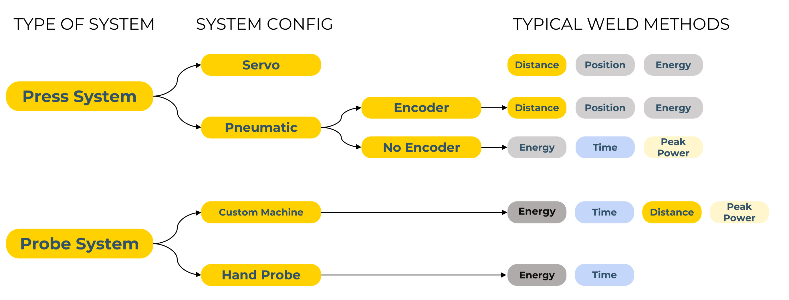
FIG 4 Typical weld method selections by equipment configuration.
Assembly requirements vary significantly. Which method you choose is a product of complex decision-making, considering which requirements take priority for your job. Many systems allow you to select multiple weld methods — essentially an either/or condition — which enable you to weld to different criteria simultaneously. This is often referred to as a secondary weld method. For example, a part that was qualified with weld by distance can also weld by position, to ensure a minimum material condition does not make an assembly “too small.”
Alternatively, process limits can be used to ensure that multiple criteria are met. These are settings within the software that allow you to identify parts welded outside of programmed parameter ranges. For example, perhaps you weld by position to ensure tight dimensional stability, but also monitor energy to flag parts that may not be sealed. Empirical testing may show that parts with less than a certain energy value consistently leak, and therefore you use that condition to identify and reject assemblies that may not meet your quality requirements. There is a multitude of ways in which you can combine weld methods, secondary weld methods, and process limits to ensure that your specific weld process is fully capable.
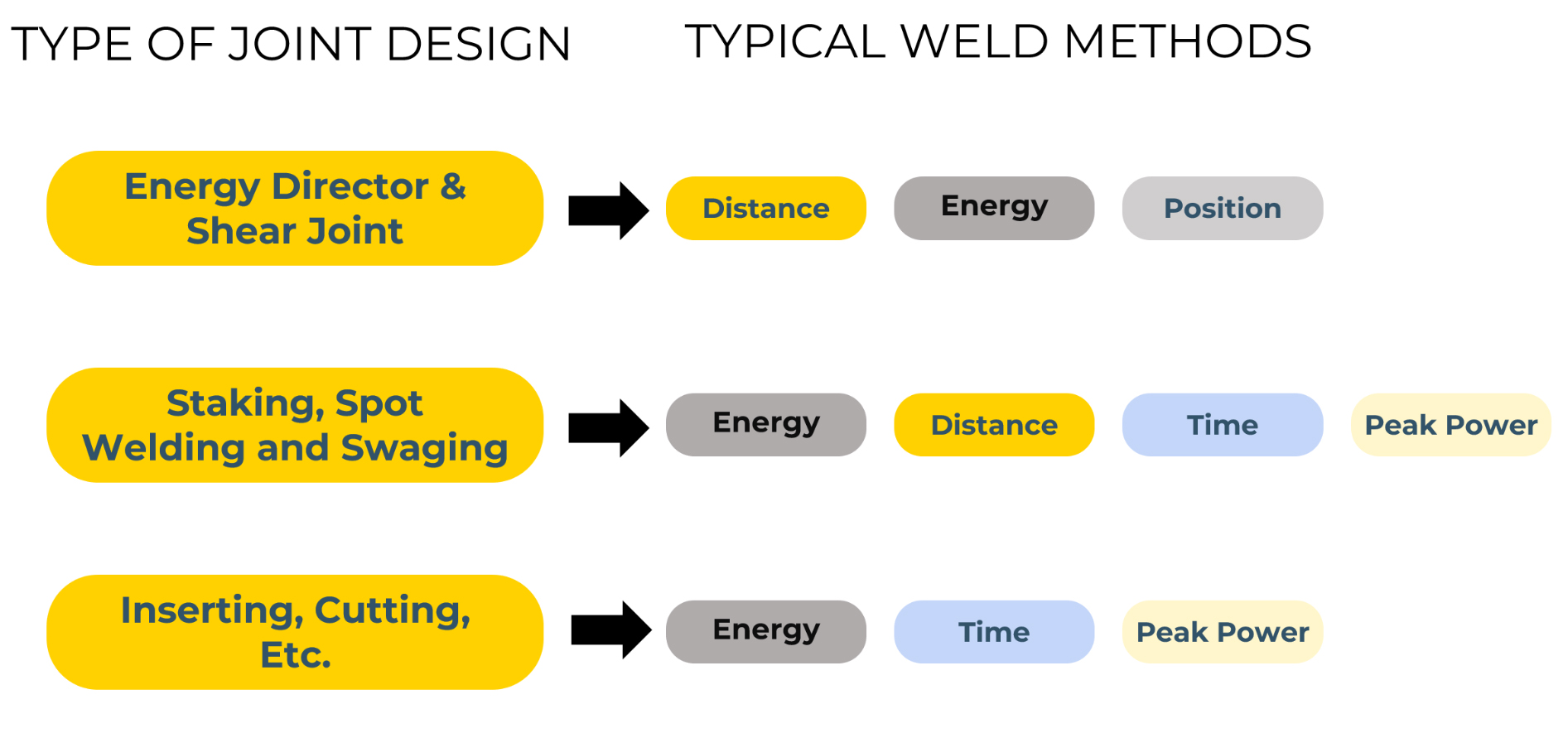
FIG 5 Example of weld method selection by assembly requirement.
Finishing the Weld Properly: The Hold Cycle
With the weld collapse now completed, the hold cycle is the final settings-related decision you must make. This controls what happens when the sonics are turned off, but before the horn has retracted. It affects how the plastic cools and solidifies. There are two basic forms: static hold and dynamic hold.
A static hold is the more traditional form of hold. In pneumatic systems, this is done under load, with air pressure applied to the part as it cools. Advanced systems allow you to control the pressure at this stage; simpler probe systems usually do not. Static hold is useful because keeping force on the weld joint during solidification allows for more consistent weld results, ensuring the joint stays fully engaged as it hardens. However, this tends to come at the expense of dimensional stability, as there is additional uncontrolled collapse during this phase that varies from part to part. This form of hold is typically ended by a set time or distance or by reaching a peak force value on the load cell.
Servo welders have the advantage of a true static hold—they hold their exact position at the end of the weld, ensuring that dimensional stability is maintained. This is useful when your assembly has a very tight finished dimensional specification; when used with weld by position, you can get incredibly precise results every time. However, this comes at the expense of not maintaining force on the weld joint during the hold cycle. To resolve this issue, servo systems employ a tool called dynamic hold.
When Dynamic hold is properly paired with trigger by force and weld by distance, the total package is the most advanced method for ultrasonic bonding today.
Dynamic hold provides the same benefits as pneumatic static hold on servo systems while maintaining precise dimensional stability. It allows for an additional programmed collapse after the sonics are turned off. This allows the benefits of keeping the weld joint under load during most of its solidification, while still tightly controlling the dimensional stability. If dimensional stability is not a primary constraint, then dynamic hold can be programmed to continue until a given force value is reached, essentially sensing when solidification is completed. This method is useful when weld quality is your primary concern, be it consistent strength or leak performance. When dynamic hold is properly paired with trigger by force and weld by distance, a part bonded on a servo welder can have both consistent weld quality and precise dimensional stability. As a total package, it is the most advanced method for ultrasonic bonding available today.
The Data ‘Footprint’ of Your Weld
The final consideration in your weld process involves collecting and analyzing your weld data. Most welding systems collect information during the weld and report it as raw numerical data and visually as graphs. This includes information on force, position, power, energy, frequency, amplitude and other key indicators. Analyzing this information is worth an entire book in itself, and you will have to wait for the sequel to this article to get the prelude to that discussion. For now, it is sufficient to note that the data contains key insights into what happens at each moment of your weld, and that ignoring it can undermine the best process controls you have selected.
In the end, every plastic assembly is unique and different. Even the best selections of tooling, equipment, trigger method, weld method, hold method and the most advanced data analysis rarely survive first contact with actual plastic parts. However, by understanding the options available to you, grasping what your machine can do, and having a strong sense of what your part needs to do, you can pivot to the right solution and achieve a capable weld process. The recommendations in this discussion are a starting point for your next ultrasonic welding project and should help guide you to the best way to weld your parts.
Related Reading: What Happened to Your Ultrasonic Weld Quality?
About the Author
David Cermak
David Cermak is a senior applications engineer at Dukane IAS LLC. He has worked on or overseen thousands of ultrasonic applications and relishes finding the right solution for welding all the new and interesting customer assemblies that cross his desk every day. Contact: dcermak@dukane.com; (630) 762-4332; dukane.com.


Related Content

How to Optimize Pack & Hold Times for Hot-Runner & Valve-Gated Molds
Applying a scientific method to what is typically a trial-and-error process. Part 2 of 2.
Read More
The Effects of Temperature
The polymers we work with follow the same principles as the body: the hotter the environment becomes, the less performance we can expect.
Read More
Formulating LLDPE/LDPE Blends For Abuse–Resistant Blown Film
A new study shows how the type and amount of LDPE in blends with LLDPE affect the processing and strength/toughness properties of blown film. Data are shown for both LDPE-rich and LLDPE-rich blends.
Read More
Improve The Cooling Performance Of Your Molds
Need to figure out your mold-cooling energy requirements for the various polymers you run? What about sizing cooling circuits so they provide adequate cooling capacity? Learn the tricks of the trade here.
Read MoreRead Next

Can Plastic Recyclates be Welded Ultrasonically?
What is possible with ultrasound? Will the result with recycled plastics material actually be worse than with standard material? Do we have to adapt our technology?
Read More
Is Your Ultrasonic Welder Up to the Challenge of Medical Processing?
New technology meets the industry’s requirements for repeatable, consistent welds in smaller and more intricate medical components. Follow these tips to make sure your equipment meets these market demands.
Read More
How to Solve Common Ultrasonic Welding Problems
Understand and address the likely origins of welding problems to keep production on track.
Read More