
Improving Twin-Screw Compounding of Reinforced Polyolefins
Compounders face a number of processing challenges when incorporating a high loading of low-bulk-density mineral filler into polyolefins. Here are some possible solutions.


Application requirements for polyolefin compounds continue to push the performance envelope with respect to improved mechanical properties such as flex modulus, tensile strength, and heat-distortion temperature; aesthetic properties such as surface quality; processing characteristics such as viscosity; and, as always, cost. Attaining those properties can require complex compound formulations, invariably involving addition of fiber and/or mineral filler reinforcement.
For many materials, one (or several) physical or aesthetic properties can improve with incorporation of fibers and/or mineral fillers, while other properties decrease, sometimes significantly. One example would be adding a high loading of calcium carbonate to PE. As the filler loading increases, tensile strength and flexural modulus both increase. At the same time, however, increased loading decreases the ultimate elongation. Another example is glass-filled PP. Again, tensile strength and flexural modulus increase with addition of glass fiber, while elongation deteriorates. The objective when producing filled and/or reinforced compounds is to balance the properties for optimum performance in the specific application.


Several parameters need to be considered when working with mineral fillers, some of which can affect the compatibility of the material with the base polymer. The particle-size distribution, surface energy, and surface treatment must all be considered. The key property, however, is the aspect ratio, which is defined as the ratio of the length of the particle to its thickness. For materials with an aspect ratio between 1 and 10, the filler acts only as an “extender” in the polyolefin, thus increasing only the stiffness of the material. When the aspect ratio is greater than 10, the filler also reinforces the polymer. This will increase the tensile strength, among other properties.
While high-aspect-ratio fillers provide some reinforcement, glass, carbon, and more recently natural fibers are the primary materials used to provide increased flex modulus and tensile strength. While most reinforced compounds are based on ¼-in. or 3/8-in. chopped fiber (primarily glass), the latest development in high-aspect-ratio incorporation is In-Line Processing Long-Fiber Technology (LFT). In this process, glass or other continuous rovings are fed into the extruder, mixed, and wetted with the polymer matrix to maintain fiber lengths in the 5 to 25 mm range. Subsequently, rather than pelletizing, the melt is directly processed into sheet or a compression molded or injection molded part.
For materials with an aspect ratio between 1 and 10, the filler acts only as an “extender” in the polyolefin, thus increasing only the stiffness of the material.
Nanocomposites have demonstrated potential to compete with glass- and other fiber-modified polymers for improving flexural and tensile properties. While nanocomposites contain usually no more than 5% loading of organoclay, they present a unique combination of compounding challenges not faced with other mineral- or fiber-filled compounds. For compounds with talc, calcium carbonate, titanium dioxide, etc., the filler has to be distributed and then dispersed into particles that need not be smaller than approximately a micron. Even when these fillers are present at 50% or higher loading, or are introduced as submicron particles, they are still processed with relative ease.
The first challenge in compounding nanocomposites is to uniformly disperse (intercalate and exfoliate) clay particles approximately 8 microns in diameter into up to a million nanometer-thick platelets. The primary difficulty is that the clay, even though it has been treated, is most likely not fully compatible with the polymer. Therefore, the task of dispersing nanoclay is similar in difficulty to trying to break rocks into dust and then dissolve the dust in water.
For reinforcement to be effective, fibers and minerals (either standard or nano-scale) each have specific compounding requirements. Fibers, whether roving or chopped, need to be unbundled and maintain a critical length during the compounding process. Minerals, depending on their structure, need to be distributed and/or dispersed and distributed. The co-rotating twin-screw compounder has long been the equipment of choice for such compounding functions. However, compounders still face processing challenges such as how to incorporate a high loading of low-bulk-density mineral filler and still maintain an economically viable production rate; how to maximize fiber length in high-viscosity, highly mineral-filled formulations; how to eliminate (or at least minimize) the possibility of contaminants such as black specks in the finished product; and how to enhance productivity.
Here is a look at approaches to meeting the specific challenges for compounding polyolefins with minerals and fibers.
PROCESSING MINERAL FILLER
Many different types of minerals are used as fillers with polyolefins. Carbonates are used extensively, the most common of which is CaCO3 which typically has a density of 2.7 g/cm³. CaCO3 improves flex modulus as well as impact strength of the final product. Stiffness and tear strength can be improved as well. Carbonates are often used in food packaging, especially with PE. In LDPE and LLDPE food packaging, carbonates can also improve water and gas barrier properties and printability.
Another mineral often used as filler for polyolefins is kaolin, otherwise known as hydrated aluminum silicates or clay. The particles typically have a hexagonal crystal structure and a particle size between 1 and 10 µm. The aspect ratio tends to be under 10, which means that this material generally would be used as a non-reinforcing filler. Kaolin can provide good electrical properties and is often added to glass-reinforced compounds.
For reinforcement to be effective, fibers and minerals each have specific compounding requirements.
Mica and magnesium hydroxide—Mg(OH)2 –are often used as reinforcing fillers with polyolefins. Mica is used extensively in automotive compounds, usually with polypropylene. Typically the result is increased tensile strength, flexural modulus, and HDT. As the filler loading increases, however, the impact resistance drops significantly, since mica tends to reduce the elasticity of the material, making it more brittle.
Talc is the softest mineral used as filler in polyolefins. The aspect ratio ranges from 2 to 20, so it can be used for reinforcement. Some typical properties that can be improved with talc are HDT and wear resistance. Talc has a hydrophobic surface, so it is very compatible with organic compounds, and it is typically used with PP in automotive applications. When working with submicron, non-compacted talc, feed limitations are often encountered. It is necessary to remove a large volume of air in order to efficiently feed the material more easily, as it tends to be too easily fluidized.
Fillers can be added to the polymer via a variety of methods:
•Adding all the filler upstream with the unmelted polymer.
•Adding a portion of the filler upstream with the pellets and adding the remainder downstream of the melting section.
•Feeding the polymer upstream, then adding the filler downstream.
While adding all of the filler with the unmelted polymer can be very effective, there are a few drawbacks. In many cases, the filler can be abrasive and would potentially cause wear on the screw and barrel elements. Additionally, if the filler is prone to fluidization or has a low bulk density (as noted for talc above), this can lead to feed-volume limitations. Also, with very high loadings of filler, it is possible to get pockets of pure filler, which can then form agglomerates in the kneading section of the screw. Distributing and then dispersing these agglomerates can be very difficult.
On the other hand, there can be difficulties associated with adding filler downstream of the melting section as well. If the molten polymer has too low a melt viscosity, the shear stress in the mixing section may not be sufficient to break up the filler agglomerates. If agglomerates become encapsulated in polymer, the “capsules” are significantly more difficult to break up in the matrix.
While adding all of the filler with the unmelted polymer can be very effective, there are a few drawbacks.
Another point that must be addressed with low-bulk-density filler is the removal of entrained air. While not directly related to mixing, entrained air may put limitations on the type of mixing design that can be used.
One example is a configuration with intense back-mixing (i.e., neutral or reverse pitch elements, which act as seals), which pushes all the air back through the additive inlet port. This causes the additive to fluidize in the screw and feed area. Fluidization limits the incorporation level and total throughput rate of the system. In order to be most successful, first distribute the additive in the polymer, and then disperse it in an almost instantaneous intensive operation. The best combination of kneading blocks or other screw elements depends on the particular polymer and filler. However, these combinations should be designed to allow air flow downstream.
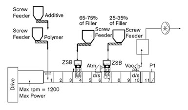
FIG 1 Process flow diagram for two-stage filler addition at high loading levels downstream of the melting section.
Figure 1 shows a barrel setup often used for incorporating very high loading of fillers into polyolefins. In this setup, filler is added in two stages downstream of the melting section. The polymer preblend along with some of the additives are fed into barrel 1. Polymer is melted in barrels 2 and 3. The first side feeder is at barrel 4, and the majority of the filler is added into this barrel. Barrel 5 is an upstream mixing zone. The second side feeder at barrel 7 is used for the remainder of the filler. Since there is an atmospheric vent in barrel 6, air from the filler in both barrels 4 and 7 can use that port to vent to the atmosphere. Dispersion of the filler occurs in barrels 8 and 9. Even when a second downstream filler addition is not required, a downstream atmospheric vent is beneficial.
Typically, fillers with high aspect ratios require different processing parameters than those with a low aspect ratio. Low-aspect-ratio fillers require the highest degree of dispersion in order to break up agglomerates. The screw configuration used depends on the filler and loading level being incorporated into the polyolefin. Kneading-block elements with narrow discs, around ½ D in length, are used to first distribute the filler. This step is necessary in order to randomize the particles in the melt before dispersing the filler. Depending on the type of filler being incorporated, wider kneading-block elements, typically 1.5 D, are then used to disperse the filler in the polymer. Higher-aspect-ratio fillers, on the other hand, require gentler handling. For such fillers, low shear is needed in order to avoid damaging the filler structure.
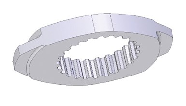
FIG 2 Patented SAM disc has a low-shear kneading disc with reduced tip width.
Narrow-disc kneading blocks are probably the most often used elements for incorporating high-aspect-ratio or structured filler. Mechanical strength of the disc limits how thin it can be. One way to circumvent the strength issue is to make the tip of the disc narrow, but leave the root thick. Figure 2 shows an individual disc from such an element. This element reduces pressure further by having the discs from the element on the opposite screw shaft offset. In this way, as the elements rotate, the two crests are offset as they pass through the apex.
Even with an optimal barrel configuration and special screw/kneading elements, incorporation of low-bulk-density fillers can be feed-rate limited and thus the extruder runs at less than economically viable production rates. However, a newer Feed Enhancement Technology (FET) gives compounders the ability to compound high loadings of low-bulk-density filler at economical throughput rates—in some instances even at the torque limits of the latest-generation, high-torque compounding extruders.
The objective of FET is to increase the feed-zone throughput capacity for hard-to-feed materials by improving the conveying efficiency through an increase in the coefficient of friction between the feed and barrel wall, thus minimizing or eliminating wall slip.
Increased friction coefficient and conveying efficiency are achieved by “adhering” a layer of feedstock material to a portion of the barrel wall through application of vacuum to a specially designed section of the barrel wall in the feed zone that is porous and permeable to the gas but not to the feed product (see Fig. 3). The pore size of the porous section of the barrel wall relative to the particle size of the powder is crucial. The optimum vacuum level applied to the device depends on particle size and shape of the feedstock.
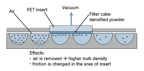
FIG 3 Feed Enhancement Technology gives compounders the ability to compound high loadings of low-bulk-density filler at economical throughput rates.
If particles were to penetrate the pores, the efficacy of the process would be reduced. However, the system is designed to back-flush particles out the pores by applying a pressure through the vacuum line(s). While powder infiltrating the porous barrel wall could be problematic, even more critical would be the presence of polymer melt or other fluid. Both of these materials would smear over the porous surface or even penetrate the pores and clog the porous structure.
By applying vacuum through the porous barrel material, air surrounding the polymer or filler is evacuated as it passes the FET barrel-section insert. As the air is sucked toward the insert, it entrains and carries the particles toward the insert surface. The air goes through but the material remains behind to coat the surface. This coating, or filter cake, of densified powder has the effect of increasing the coefficient of friction between the wall surface and the bulk of the material. The layer of material adhering to the barrel wall due to the vacuum is continuously renewed by the rotating screws. Additionally, the bulk density of the powder is increased as it passes the insert. These two effects combine to improve the conveying efficiency.
Incorporating FET can improve the overall production rate for a compounding line. However, there are other impacts of the technology. For example, increasing the rate of the compounding line while all else remains the same results in a lower overall energy consumption per unit of product produced. Lower unit energy translates into lower product temperature, which in turn would mean less potential for material degradation or stabilizer package consumption.
PROCESSING FIBER REINFORCEMENTS
Successful incorporation of high-aspect-ratio additives requires separating any dispersive mixing operation from the highly distributive mixing. This is most easily accomplished by downstream feeding the reinforcement after polymer melting. However, this is only the first step. The three critical operations for fiber processing are feeding, mixing, and pressurization/discharge.
It has been shown that fiber aspect-ratio attrition occurs through fiber-fiber interaction, the frequency of which increases proportionately with the volume fraction of fiber. Although not the only reason, this helps explain glass-length differences in various polymers that have identical weight-percent glass loading. For example, 30% by weight fiber in PP is a lower volume fraction than 30% in nylon 6/6. This corresponds to experimental results showing longer glass length in PP.
Successful incorporation of high-aspect-ratio additives requires separating any dispersive mixing operation from the highly distributive mixing.
Based on this concept, the potential exists for glass to be attenuated as it is fed into the system. As glass is transported from the feed location to the mixing section, there is a dwell time where the glass is essentially interacting only with itself and is therefore potentially causing fiber attrition. The mixing section must accomplish two tasks. It must break up the fiber bundles (if fed this way), distribute the glass, and wet the glass with the polymer. Gentle distribution of glass without wetout does not accomplish the main objective of producing a reinforced plastic.
The discharge section of the extruder must pressurize and strand the polymer for pelletizing. This puts additional mechanical work into the system, which can further attenuate the fibers. However, with properly wetted-out compound and streamlined die design, this operation can be achieved without significant additional fiber breakage.
The proper setup for maximum retention of fiber length depends on the matrix polymer, fiber type, compatibilizer, and percent loading. The glass is introduced through a twin-screw feed device located downstream from the polymer melting section. The temperature of the polymer and glass should be controlled so that minimum polymer viscosity change occurs during glass introduction. Either heating the polymer above normal level or heating the glass are possible approaches.
The mixing section should consist of distributive mixing elements, either narrow-disc kneading blocks or toothed mixing elements (TME). The latter produce significantly greater glass lengths and a narrower length distribution. Some experiments, however, have indicated little or no difference in resulting toughness and impact properties of the material produced on kneading-block or TME-based screw configurations. Subsequent research has shown significant improvement in physical properties using a mixing configuration based on ZME elements, discussed below. Therefore, even though it is generally acknowledged that the toothed mixing elements do not attenuate the glass fiber, it has not been shown that this alone correlates with improved physical properties. The glass must also be totally wetted out.
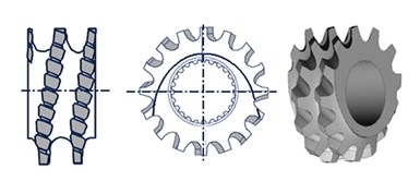
FIG 4 The ZME element is designed with a number of teeth around the circumference at a certain angle. The base pitch is reverse-conveying while the teeth are forwarding.
The purpose of the ZME element is to achieve high distributive mixing and low dispersive mixing. It is designed with a number of teeth around the circumference at a certain angle. The element itself is overall forwarding. The base pitch is reverse-conveying while the teeth are forwarding, as shown in Fig. 4. With the exception of the tooth root, the element is designed to be self-wiping, which can prevent degradation of material when compared with elements that do not wipe the barrel wall. The reduced diameter also increases clearance for flow. Using ZME elements has been demonstrated in our lab to benefit processing of glass-reinforced polyolefin by preserving the fiber length with lower energy input.
It has been known since almost the beginning of twin-screw compounding that proper screw design is important to successfully compound a fiber-filled polyolefin. For example, a work published almost 35 years ago demonstrated that a polyolefin with a fiber loading of 40% or more required a low-intensity screw design in order to preserve fiber length.
VACUUM VENT PERFORMANCE
The performance capability of twin-screw compounding extruders with a conventional top-vent barrel can be limited in many cases, especially in compounding low-viscosity melts and extrusion processes requiring removal of high volumes of vapor. Vent fouling (material flowing out of the vent opening) and black specks in the compound are two major issues that processors want to avoid. Vent fouling is a potential source of lost production and of product contamination. Operators have to constantly monitor the vent. If it gets fouled, then they have to take the time to clean it out.
Even after the vent is cleaned out, there is material left behind. After a period of time, this material will degrade and char. At some point, there is a good chance that it will dislodge and fall into the compound, resulting in black specks. Even if the vent does not foul, there is potential for vapors to condense on the vertical wall of the vent dome. Again, over time, this material will degrade and char and most probably dislodge and fall into the compound, causing black specks.
Even after the vent is cleaned out, there is material left behind.
The ZS-EG twin-screw side degassing provides a solution. With its large free cross-section for devolatilization, it keeps the melt in the processing section without product escape, even for processes with a high degree of fill. Fumes or gases are removed reliably through the axially open screw flights. Increases in the throughput rate of up to 30% with improved product quality have been achieved.
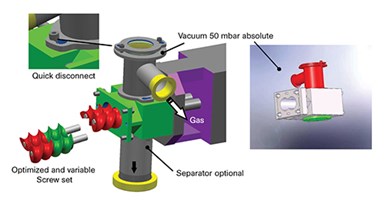
FIG 5 Through its connection to the side of the compounding unit, the ZS-EG side-vent stuffer inherently prevents material from falling back into the extruder from the vent. Also, the stuffing action of the screw prevents the vent from fouling.
By the nature of its connection to the side of the compounding unit, the ZS-EG side-vent stuffer (Fig. 5) inherently prevents material from falling back into the extruder from the vent. Also, the stuffing action of the screw prevents the vent from fouling. This permits operators to concentrate on other aspects of the compounding process. Additionally, it has the potential to permit the compounding line to run at higher rates that previously would have resulted in fouling the top-vent design.
ABOUT THE AUTHORS
Paul Andersen is director of process technology for Coperion Corp., Ramsey, N.J. He has 35 years of industrial experience and holds several patents related to twin-screw compounding. He has worked extensively on compounding of multi-phase engineering polymers, including nanocomposites and fiber reinforced materials. Contact: (201) 327-6300; email: paul.andersen@coperion.com; web: coperion.com.
Andrea Lim is a process engineer for Coperion. She works with clients to organize and execute tests in the compounding lab. Her areas of responsibility include engineering plastics, polyolefins, and masterbatch. Contact: andrea.lim@coperion.com.
Kim Young is a process engineer for Coperion. She has 15 years of industrial experience, most of it in plastics, both as a formulator as well as in processing. Her primary responsibility is to organize and execute tests for clients in the compounding lab. Contact: kim.young@coperion.com.


Related Content

How to Set Barrel Zone Temps in Injection Molding
Start by picking a target melt temperature, and double-check data sheets for the resin supplier’s recommendations. Now for the rest...
Read More
PBT and PET Polyester: The Difference Crystallinity Makes
To properly understand the differences in performance between PET and PBT we need to compare apples to apples—the semi-crystalline forms of each polymer.
Read More
How Much L/D Do You Really Need?
Just like selecting the extruder size and drive combination, the L/D should be carefully evaluated.
Read More
The Importance of Melt & Mold Temperature
Molders should realize how significantly process conditions can influence the final properties of the part.
Read MoreRead Next

How Polymer Melts in Single-Screw Extruders
Understanding how polymer melts in a single-screw extruder could help you optimize your screw design to eliminate defect-causing solid polymer fragments.
Read More
Understanding Melting in Single-Screw Extruders
You can better visualize the melting process by “flipping” the observation point so that the barrel appears to be turning clockwise around a stationary screw.
Read More