
10 Ways to Improve Twin-Screw Compounding Performance
There are many techniques known to operators and plant engineers for increasing the performance of a twin-screw compounding extruder.


There are many techniques known to operators and plant engineers for increasing the performance of a twin-screw compounding extruder. Because of their informal nature, however, most of these methods do not appear in any equipment manuals. Nor are they generally mentioned in textbooks and technical papers. But sometimes attention to several small details can add up to make a big difference in extruder performance. The tips described in this article fall into three broad categories: processing techniques, machine modifications, and maintenance procedures
1. Thermal Insulator Gaskets
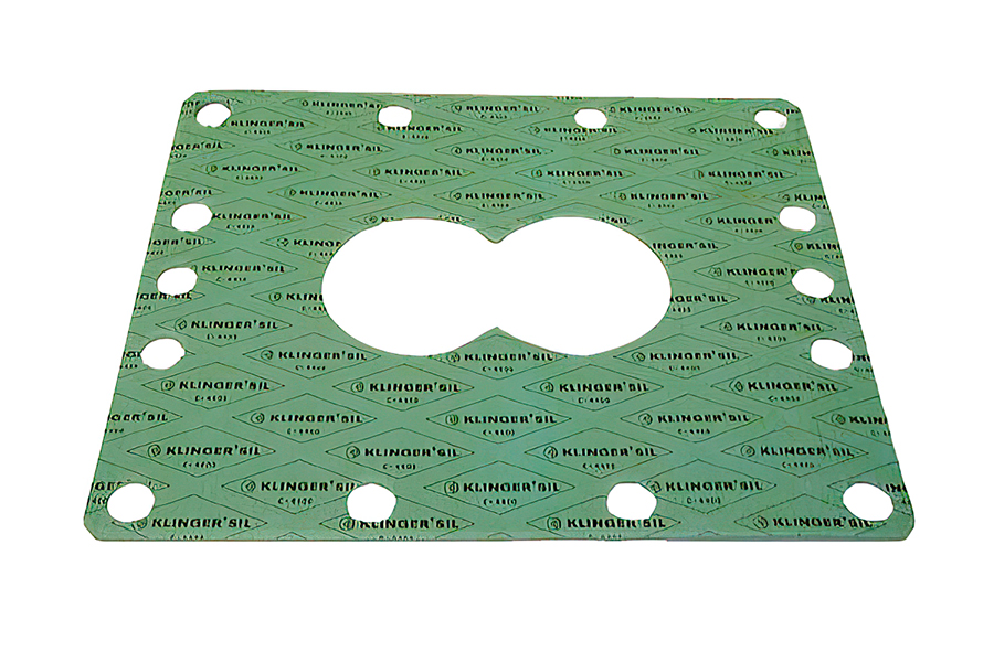
One way to keep the heat from barrel section 2 from transferring to the water-cooled first barrel section is to install an insulator gasket between the flanges of the two.
Photos: LeistritzThe feed barrel section is almost always water cooled. But because this barrel is bolted flange to flange against Barrel Section 2, which is heated, heat is continuously transferred from the hotter to the cooler barrel section. As a result, Barrel 2 is often not able to maintain a high enough temperature. In a typical case, the operator has a setpoint of 180 C for Barrel 2 but can never get above 135 C because of heat loss to the feed barrel.


The easiest solution is to install an insulator gasket between the flanges of the feed barrel and Barrel 2. These gaskets are typically 1-mm thick, and we recommend stacking two together for better insulating performance. There will still be some heat conduction through the bolts and the screw shafts, but not nearly as much as without the insulation.
New extruders are often supplied with the insulator in place, but many operators don’t realize its importance and throw it away when disassembling the barrels. After several years the insulator gasket should be replaced, as the material tends to degrade and crumble.
2. Side Stuffing of Powders
Side stuffing is widely used for feeding fillers into twin-screw extruders. Many processors desire very high loadings of fillers that are often low-bulk-density (fluffy) materials. The ultimate loading attainable is usually limited by two parameters:
A) Volumetric capacities of the side-stuffer and main extruder screws. The volumetric capacity is based on the free volume of the side-stuffer’s twin screws and of the main extruder screws, as well as the rpm of both screw sets. If material is test run through the side stuffer unbolted from the extruder and discharging into a drum, it probably will easily feed a high rate of material. But when the stuffer is attached to the extruder, capacity is often limited by the amount of material the main extruder screws can accept.
Consequently, it is best to for the main extruder screws to have flighted elements with a long pitch (long flight advance) at the stuffer location, extending 2D to 4D downstream of the stuffer. This is to keep the melt in the extruder moving rapidly forward to allow the maximum free volume for the filler to enter. If the screw design causes any “dam-up” of material downstream of the stuffer, it will severely limit the amount of filler that can be fed.
B) Venting capacity to allow air to escape the extruder. The object of venting is to allow air to escape easily, while preventing large amounts of filler from being lost out the vent. The best configuration is a top vent in the barrel immediately upstream of the side stuffer. Sometimes a small half-slot vent insert can also be used in the top of the side stuffer.
Here are some other factors to consider:
- Feeder drop height: Ideally, the feeder should be positioned as close as possible above the side stuffer to minimize the drop height. If a fluffy material is allowed to drop through air, it becomes aerated to the point where its bulk density is significantly reduced. This can limit the throughput rate of the entire line.
- Feeder agitation type: Make sure the agitator in the filler feeder isn’t aerating the material and reducing the bulk density. Many feeder manufacturers have special agitator designs for powders.
- Make sure stuffer hopper is vented: Along with the filler, the stuffer also introduces a lot of air into the extruder. An open top on the side-stuffer chute will take care of venting. If you have a solid cover on the chute with a round stubup and flex connector to the feeder, it’s important to also have a vent opening.
- Ground all hoppers/chutes to drain static electricity: Some materials generate static electricity from friction. Static charge can cause powder to cling to the inside surfaces of hoppers and chutes, leading to problems such as caking. An easy fix is to run a ground wire (10 gauge is recommended) from the chute to a known good ground on the machine frame.
- Compressed-air blaster: If caking persists, sometimes a special solution is needed. Hopper vibrators can be used, but are tricky to size and mount. An alternative is a “blaster” with air-jet nozzles strategically placed within the wall of the chute to break up any cakes before they get too large. The air jets are connected to a solenoid valve, which is actuated by a repeat cycle timer. This lets you set both the blast period and dwell time between blasts. It’s best to have a small air accumulator tank just upstream of the solenoid valve to provide a sharp pulse of air.
3. High-Pressure Water Pumps
It’s well known that turbulent flow in a pipe will induce far greater heat transfer from the pipe wall than will laminar flow. Laminar flow occurs with low fluid velocities caused by low-pressure delivery. In a laminar-flow situation, a stable boundary layer develops, which acts just like an insulator between the main fluid flow and the pipe wall. “Layers” of fluid slide over adjacent layers, without mixing and without removing much heat.
With turbulent flow induced by high-pressure delivery, there is a high degree of transverse momentum exchange, which breaks up the boundary layer. As a result, the violent fluid motion causes much greater heat transfer from the pipe wall to the fluid.
The easiest way to induce turbulent flow in the barrel cooling bores is to increase the delivery pressure. Extruder cooling recirculation systems typically have supply pressures from 20 to 60 psi. To achieve turbulent flow, a pressure of approximately 120 psi is desired. This can be attained relatively easily by changing the pump in the recirculation system to a high-pressure type. Almost all extruder cooling system components (hoses and valves) are rated for at least 150 psi, so 120 psi still allows some safety factor.
The advantage will be apparent immediately in a process that is highly exothermic. Temperature zone overrides can often be greatly reduced or even eliminated. A side benefit of turbulent flow is that it inhibits fouling of the cooling bores from scale buildup.
4. Acid-Flush Cooling Bores
Water-cooled extruder barrels are heat exchangers, and like all other heat exchangers the coolant bores are subject to fouling from scale buildup. Most operators notice that the cooling performance of a new extruder is much better than an extruder after three or four years of running. This is because the new extruder barrel has smooth, shiny, fresh-drilled cooling bores. The older machine has a layer of crusty mineral deposits lining the bores, which act like an insulator.
If left unchecked, scale buildup can lead to a much more serious problem. Eventually the cooling bores can become completely blocked so there is zero water flow. If this happens, the only solution is to remove the barrels from the extruder and drill out all the cooling bores—a time-consuming procedure.
5. Use Synthetic Gear Oil
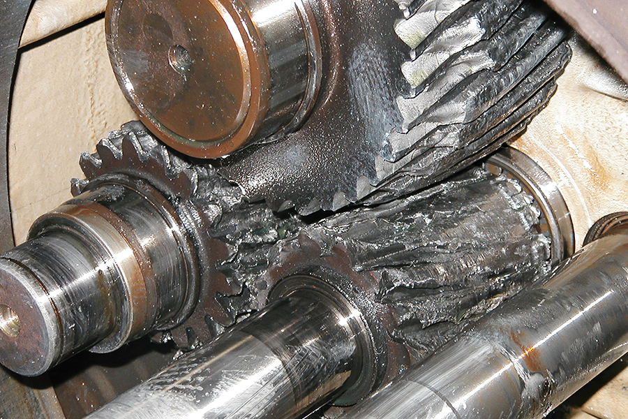
Switching to synthetic lubricating oil for gearboxes will help gears, bearings, and seals last longer. The gearbox will also run cooler and quieter.
The gearbox is the heart of a twin-screw extruder. If it fails, it’s likely to be expensive to repair, and it may take quite awhile. There is one thing everyone can do, easily, to avoid gearbox problems: switch to synthetic gear oil. Synthetic oil is a huge advance in lubrication technology:
- It’s more “slippery,” resulting in less friction
- Gears, bearings, and seals last longer.
- The gearbox runs cooler and quieter.
- Synthetic oil doesn’t lose viscosity from mechanical shear.
- It maintains higher viscosity at high temperatures.
- It improves the overall efficiency of the gearbox.
6. Use Anti-Seize Lubricants
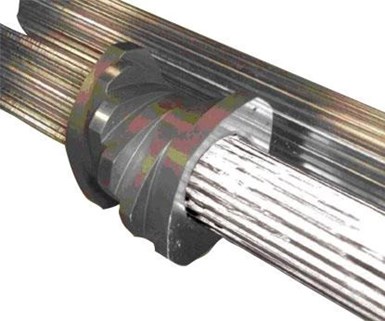
Long-lasting anti-seize lubricants make it much easier for operators to remove screw elements from shafts.
Most people in plastics are aware of the need for anti-seize lubricants. There are several different types: copper-based, molybdenum, lithium, etc. For something like a bolt thread, probably any type will work. But for extruder spline shafts the choice of anti-seize is much more critical.
Screw elements fit onto the spline shafts with a very small gap tolerance, but low-viscosity polymers tend to creep down between adjacent elements and get into this gap. With time and heat, degraded polymer forms a high-strength adhesive just like an epoxy. If screws are left together in an extruder without being taken apart periodically, they can be extremely difficult to remove from the shafts. This is why the choice of anti-seize is so important.
Many types of anti-seize lubricant are acceptable for a short period of time, but over long periods at high temperature, they degrade into a fine powder. This makes them a poor choice for spline shafts, where you need the anti-seize to perform when you’re ready to disassemble the screws months or years later.
After testing all the anti-seize brands on the market over a period of many years, Leistritz has found one that is ideal for this application: Fuchs Gleitmo 820, manufactured by Fuchs Lubricants in Germany. Gleitmo 820 is a white grease containing high solids. It is very slippery and is rated for up to 1150 C. What makes it perfect for spline shafts is that it doesn’t degrade into a powder. When the screw elements are removed after months of use, the Gleitmo 820 is still a slippery grease. Fuchs Lubricants has U.S. distributors and a website (fuchs.com) with technical information.
7. Purge Often
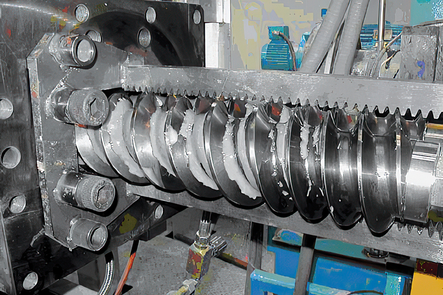
Purge often to prevent old materials from being “baked on” the metal surfaces.
Purging is widely used as an easy way to clean out materials from the extruder and die and to avoid a time-consuming stripdown cleaning. There are many types of materials used for purging, both commercial purge products and “home engineered” purges. These materials generally fall into two categories: chemical purges and mechanical abrasive purges. Many combine both chemical and abrasive actions.
Chemical purges work by attacking the plastic residue like a solvent. Many of them also incorporate a foaming action and require a 5-min “soak” in the barrel to allow the chemical action to work.
Mechanical abrasive purges work by scouring and scrubbing material off the metal surfaces, using friction and shear.
Processors do a lot of trial-and-error experimentation to find the right purge material and technique. No “magic” purge material will work best for all materials. Commercial purge products are generally more expensive than “home engineered” purges. But if you can use less material with the commercial purge, or get the job done quicker, the total cost may actually be less.
Processors have run all sorts of materials through extruders, in the quest for a cheap and effective purge material. For instance, in the U.S. Midwest many operators use cattle-feed corn, because it’s readily available and does a fairly good job of scouring out the machine. Here are two effective homemade purges:
- Mix #1: 50% HDPE (or another high-viscosity resin) + 50% diatomaceous earth (DE): DE is finely milled fossil shells of tiny sea organisms. It is readily available in garden supply stores. DE looks like a fine powder, but the particles have very sharp, angular edges, which produce a scouring action. Processors who run sheet and film use this purge, as it can sometimes get rid of die lines, saving a lengthy die teardown.
- Mix #2: HDPE or other viscous resin with kitchen cleanser and water: Mix a slurry of water and three or four cans of Comet or Ajax kitchen cleanser in a bucket. Feed HDPE at a normal purging rate and temperature, and slowly pour the slurry into the main feed port. The water in the slurry will flash to steam, which gives a very good cleaning effect combined with the abrasive in the kitchen cleanser. (Safety note: Warn any operators nearby that steam may discharge from extruder openings. Do not look into the die or vents unless wearing a full polycarbonate face shield and long-sleeved shirt.)
Probably the most important thing is to purge often. The object is to prevent old materials from being “baked on” the metal surfaces. Once this happens, purging will generally not be able to remove the material, and a manual stripdown cleaning will be the only remedy.
One mistake many processors make is to run the purge only at a fixed screw rpm. It’s much more effective to vary the speed, changing from low to medium to high rpm, running for perhaps 30 sec at each speed. This induces different shear rates against the metal surfaces, helping to dislodge old material from the walls.
8. Efficient Changeovers
Color or material changeovers tend to create problems. Extrusion people would like to always have nice long runs. But in the real world, demands from customers mean frequent changeovers to make 80 lb of Product A, followed by 200 lb of Product B, etc. So it is important to approach changeovers in a way to minimize operator effort and problems:
- Know how critical is cleanliness to the next product to be run. There are anecdotes around any extrusion shop of somebody purging for 16 hr to avoid pulling the screws to brush them off. The point is, if you know the next product requires a thorough manual brush cleaning, don’t waste time and material trying to get by with purging.
- If possible, plan runs in order of decreasing cleanliness requirements. For example, this means going from light to dark colors. That way, you should face only one difficult changeover, when going from the dark color back to a light color.
- Have written purging or strip-down procedures to run each product. This helps operators plan their time, and eliminates discussions later on about how many pounds of product have to be scrapped because the operator didn’t clean the machine properly.
- Use the right size extruder for the lot size. This may seem obvious, but many processors don’t plan runs for the right machine and end up running a 500-lb lot on a 75-mm extruder, producing 300 lb of scrap while getting it to run correctly.
- Help operators by organizing the necessary tools, cleaning supplies, screens, die plates, etc. near the extruder. If frequent changeovers are required, set up a workstation to have everything the operator needs right by his side.
- Study raw-material and end-product flow in and out of the process area. Try to arrange it for minimal operator effort. The less operators have to move drums and gaylords around, the more they can concentrate on maximizing running time.
9. Warm-Up/Cool Down
Extrusion people tend to keep the machinery hot all the time. Operators typically turn the heat zones on the minute they come in the plant at 7:00 am. If you’re really going to start the extruder at 8:00 am, there’s nothing wrong with this. But often people get distracted with maintenance chores, and the extruder sits idle, heated to full operating temperature for hours at a time.
This is a bad practice because it allows polymer to bake onto the screws and barrels. Once baked on, the material will continue to degrade and carbonize. Purging will not remove this material. Even worse, as the extruder is running product, black specks will periodically flake off the screws and barrels, contaminating the product and causing customer complaints.
The best way to handle warm-up is to plan for when you really want to start running the extruder. Then start heating up only as soon as will allow for complete warm-up plus adequate soak time.
There are also preferred shutdown/cooldown procedures to avoid problems with black specks. Before shutting the extruder down, it’s good practice to fill the extruder and die to the maximum degree with some inert polymer such as HDPE to “seal” the machine. The HDPE displaces oxygen, and coats the metal surfaces to greatly slow down oxidation and formation of carbon.
After the extruder has been “sealed,” it is better to crash cool the machine, rather than let it cool just from exposure to ambient air over the next 18 hr. Crash cooling involves turning all the temperature setpoints down to zero to force the cooling solenoid valves to open. With the coolant pump running, this will force cool water through all barrel sections, bringing the temperature down quickly. Quick cooldown doesn’t give the polymer a chance to degrade and carbonize.
10. Key Process Indicators
Most extruder operators tend to be like old-time pilots, preferring to fly by the seat of their pants. And many of them have excellent instincts for knowing when the process is running right and when it is not. But as products get to be more complex, with tighter processing windows, it is much better to have some kind of quantitative way of assessing how the machine is running.
A common example is when the operator is convinced something is different about the material. The line is just not running the same. If the material supplier is contacted, it will probably say its QC records show that the material is the same as it’s always been. Without some real numbers, how can you prove to the material supplier, and to yourself, that the material is indeed different?
• Indicator #1: Specific throughput
Specific throughput (kg/hr ÷ rpm = kg/hr/rpm) is proportional to the degree of fill. Degree of fill is useful especially if records are kept over a period of time for many different products, as it can help you predict how best to run a new product. It also helps you plan machine hours, as a product that needs a low degree of fill will take longer to run a certain lot size. Finally, degree of fill is helpful in scaling up (or down) runs on different size extruders.
• Indicator #2: Specific Energy
This has to be calculated in two steps:
Kw (applied) = kW (motor rating) × % torque × running rpm × 0.97 max. rpm.
Specific Energy = kW (applied) ÷ kg/hr
Specific energy defines how much power is being expended, and the mechanical work being performed, to process each kg of material. Again, it is useful to keep records of this figure for specific products over a long period of time. Operators will get to know which products are “energy hogs” and which aren’t. This will help in planning runs for new products and in estimating the production capacity of any given line.
Specific energy is also helpful in pinpointing problems. If a product always runs with a specific energy around 0.25 kW/kg/hr and one day it’s only running 0.16 kW/kg/hr, if all other conditions are the same this would be a reason to suspect the material.
About the Author: Bert Elliott has held various manufacturing and engineering positions with extruder OEMs since 1981, and has been engineering manager at Leistritz, Somerville, N.J., since 1993. Over the last 28 years he has been involved in more than 1000 extruder installations. Contact him at (908) 685-2333 • leistritz-extrusion.com.


Related Content

What to Know About Your Materials When Choosing a Feeder
Feeder performance is crucial to operating extrusion and compounding lines. And consistent, reliable feeding depends in large part on selecting a feeder compatible with the materials and additives you intend to process. Follow these tips to analyze your feeder requirements.
Read More
Green’s the Theme in Extrusion/Compounding
The drive toward circular economy is requiring processors to make more use of PCR. Machine builders at K—across all extrusion processes—will be highlighting innovations to help them do just that.
Read More
Sustainability Among the Many Niches at Niche Polymer
Founded in 1987, Niche Polymer continues to grow—both organically and through acquisition—by focusing its product-development efforts on ever-changing market needs. Adding value to both industrial and post-consumer scrap is a growing part of this effort.
Read More
LFT-D Thrives in Automotive and Other Durables
Teijin Automotive acquires its 10th direct long-fiber thermoplastic system as demand for this technology soars.
Read MoreRead Next

Advanced Recycling: Beyond Pyrolysis
Consumer-product brand owners increasingly see advanced chemical recycling as a necessary complement to mechanical recycling if they are to meet ambitious goals for a circular economy in the next decade. Dozens of technology providers are developing new technologies to overcome the limitations of existing pyrolysis methods and to commercialize various alternative approaches to chemical recycling of plastics.
Read More
People 4.0 – How to Get Buy-In from Your Staff for Industry 4.0 Systems
Implementing a production monitoring system as the foundation of a ‘smart factory’ is about integrating people with new technology as much as it is about integrating machines and computers. Here are tips from a company that has gone through the process.
Read More
Troubleshooting Screw and Barrel Wear in Extrusion
Extruder screws and barrels will wear over time. If you are seeing a reduction in specific rate and higher discharge temperatures, wear is the likely culprit.
Read More