
How To Design Three-Plate Molds – Part 4
There are many things to consider, and paying attention to the details can help avoid machine downtime and higher maintenance costs — and keep the customer happy.


As I mentioned in Part 3 of this series, the parting line between the runner stripper plate and the injection clamp plate cannot start to open until the opening between the runner stripper plate and the A-plate is fully open. Otherwise, the runner may not have enough room to fall freely out of the mold. It’s not common for the runner stripper plate to advance prematurely, but from time to time it might. Therefore, some method should be incorporated to prevent that from happening.
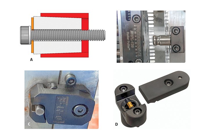
FIG 1 Various plate retention devices. Source: J. Fattori
On small- to medium-sized molds, friction pullers, roller pullers, slide retainers and plate retainers (as shown in Figure 1) work well for preventing the runner stripper plate from advancing prematurely. Note: Friction pullers are available in many different types and designs. The one shown in Figure 1 is my proprietary design.


For larger molds, die springs are frequently used to retain the runner stripper plate, as shown in Figure 2. At least two or four retainers are required to achieve sufficient holding force, as well as preventing the plate from cocking when it advances.
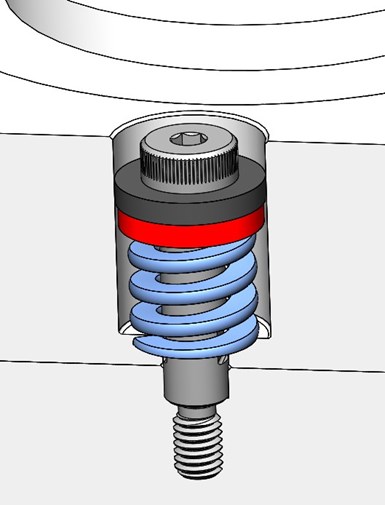
FIG 2 Die spring used to retain a plate.
Sucker or Puller Pins
The function of a sucker pin in a three-plate mold is similar to a sucker or sprue puller pin in a two-plate mold. In a three-plate mold, the sucker pins pull the runner, and the runner drops out of the back of the floating A-plate and retains them on the runner stripper plate until the stripper plate extends forward.
There are several methods and variations on how to install a sucker pin, as shown in Figure 3. The first, labeled A, is strictly a sucker pin riding in a round through-hole in the runner stripper plate. The pin is held in place with a set screw impinging on the head. This method is very common — probably because it is the cheapest. In my opinion, this design should only be used for low- to medium-volume molds.
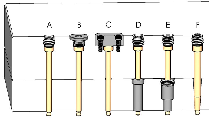
FIG 3 Various designs and installation methods for sucker pins.
The second method, labeled B, is the same as method A, but is retained with a core pin retainer. The advantage of the retainer is, when properly installed, it enables the pin to float sideways a little. In the event of any misalignment from thermal expansion, bushing wear or machining errors, it reduces the amount of wear on the pin’s through-hole.
Sucker pins should protrude beyond the face of the runner stripper plate.
The third method, labeled C, is the same as method B, but with a plate behind the pin instead of a retainer. This plate can also be machined to enable the pin to float. The advantage of a plate is that it can retain several sucker pins, thereby reducing the amount of machining required.
The fourth method, labeled D, is a sucker pin riding in a hardened bushing —typically a drill bushing. A hardened bushing virtually eliminates any wear in the bore. The bushing needs to be retained with a screw, retaining ring or some other method. A press fit is usually not desirable because it can come loose over time.
The fifth method, labeled E, is similar to method D, except that the sucker pin is riding in a patented sucker pin bushing which has a threaded head. The advantage of this method is that the threaded head secures the bushing in place. The sixth method, labeled F, is a tapered sucker pin seated in a tapered hole in the runner stripper plate. When properly fitted, this design eliminates the possibility of any down-flash because there is zero clearance between the pin and the bore hole.
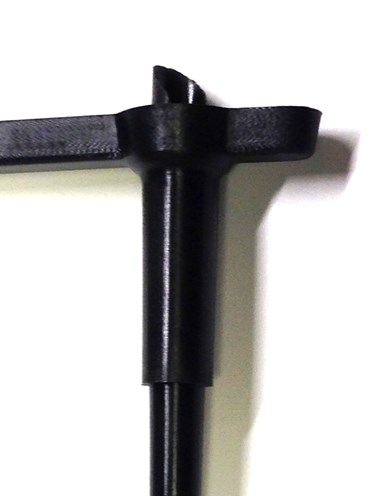
FIG 4 Down-flash on a sucker pin.
If, over time, you get wear in the bore hole in designs A, B or C, you can repair it with an oversize core pin. If you get wear in designs D or E, you can replace the pin or bushing. If you get wear in design F, you can resurface the tapered hole and advance the core pin. Methods D, E and F add a little cost to the mold, but they extend the life of the pin and reduce the risk of down-flash as shown in Figure 4. Keep in mind that you can use various combinations of these sucker pin designs, as well as their installation and retention methods.
There are several methods of installing a sucker pin.
The contour at the tip of a sucker pin can have various shapes, as shown in Figure 5. The shape of the first two pins on the left are the most common. The third pin with the conical tip is designed to reduce material flow disruption of the melt stream, which can be critical with heavily filled and viscous resins. The pin on the far right was designed to reduce some of the mass at the intersection of the runner and a large diameter runner drop in order to reduce the cycle time, as shown in Figure 6.
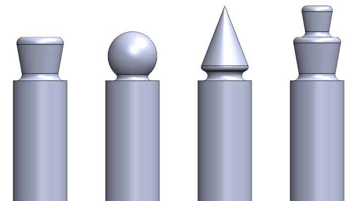
FIG 5 Common shapes for a sucker pin tip.
Sucker pins should protrude beyond the face of the runner stripper plate by 0.002 inch to 0.020 inch, as shown in Figure 7. If a pin is even slightly below the surface of the runner stripper plate, it can cause the runner to hang up in the mold.
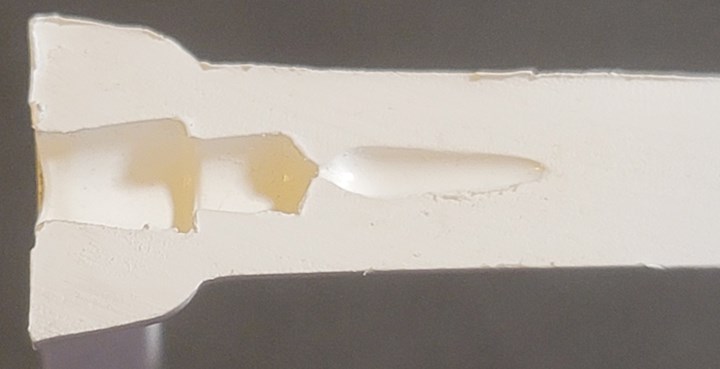
FIG 6 A cored-out runner drop.
One trick that I have seen is the addition of a 30-degree or smaller chamfer around the bore hole of the sucker pin, as shown in Figure 8. The idea is that the chamfered area will solidify quickly and reduce the chance of down-flash into the bore hole. In a way, this chamfer acts as a runner flash trap, which I discussed in Part 3 of this series. The chamfer also makes the length of the sucker pin less critical, and the 30-degree angle ensures the runner will not hang up in the stripper plate.
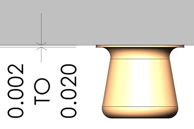
FIG 7 Sucker pin protrustion
The amount of undercut required to pull a runner drop out of an A-plate depends on a several factors, but the primary ones are material type, cycle time and cooling. The softer the material, the larger the undercut is required. The material can be soft due to its inherent hardness, such as with olefin or elastomeric materials. It can also be soft if the mold opens before the runner has time to completely solidify.
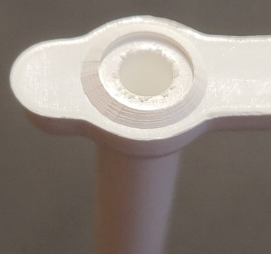
FIG 8 Chamfered edge around a sucker pin bore hole.
Conversely, the material can be very rigid if it contains a filler, such as glass or mineral, or if the cycle time is excessively long. Rigid runners with aggressive undercuts can cause flakes which can hob both the runner stripper plate and the A-plate, as shown in Figure 9. My suggestion is to initially be aggressive with the amount of undercut, because if you encounter tearing or flaking during the first mold sampling, it is steel-safe to make it less aggressive.
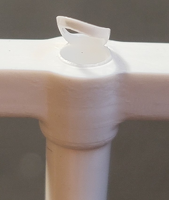
FIG 9 Flake formed from an aggressive undercut.
About the Author: Jim Fattori is a third-generation injection molder with more than 45 years of molding experience. He is the founder of Injection Mold Consulting LLC. Contact jim@injectionmoldconsulting.com; injectionmoldconsulting.com.


Related Content

How to Set Barrel Zone Temps in Injection Molding
Start by picking a target melt temperature, and double-check data sheets for the resin supplier’s recommendations. Now for the rest...
Read More
How to Stop Flash
Flashing of a part can occur for several reasons—from variations in the process or material to tooling trouble.
Read More
How to Mount an Injection Mold
Five industry pros with more than 200 years of combined molding experience provide step-by-step best practices on mounting a mold in a horizontal injection molding machine.
Read MoreRead Next
Why (and What) You Need to Dry
Other than polyolefins, almost every other polymer exhibits some level of polarity and therefore can absorb a certain amount of moisture from the atmosphere. Here’s a look at some of these materials, and what needs to be done to dry them.
Read More
Processor Turns to AI to Help Keep Machines Humming
At captive processor McConkey, a new generation of artificial intelligence models, highlighted by ChatGPT, is helping it wade through the shortage of skilled labor and keep its production lines churning out good parts.
Read More
How Polymer Melts in Single-Screw Extruders
Understanding how polymer melts in a single-screw extruder could help you optimize your screw design to eliminate defect-causing solid polymer fragments.
Read More