How to Design Three-Plate Molds, Part 1
There are many things to consider, and paying attention to the details can help avoid machine downtime and higher maintenance costs, and keep the customer happy.


Three-plate molds have significantly more design considerations that affect their cost, functionality and longevity. That’s why it is especially important to pay attention to every detail, as well as having a thorough and collaborative mold design review.
What is the mold going to make? Is it a one-cavity flower pot or 128-cavity syringes? Or is it something in between? When it comes to three-plate molds, or any mold for that matter, it’s not what the mold is going to make. It’s how many cycles are expected over the course of the mold’s life span. That’s what dictates how a mold should be designed and built. It may need a little more attention to the details and a little more initial cost to be profitable in the long run. Details can help avoid machine downtime and higher maintenance costs. They also help to keep the customer happy and foster the chances of future business.


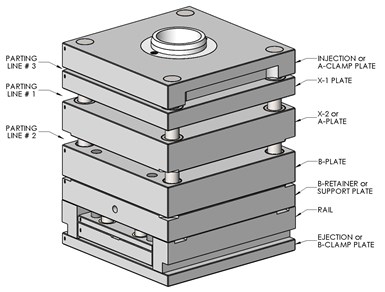
FIG 1 A T-Series mold base. Images: J. Fattori
The type of mold base specifically designed for three-plate molds is called a T-Series mold base, as shown in Fig. 1. A T-Series mold base is similar to an A-Series mold base, but with an additional plate between the Injection Clamp Plate and the A-Plate. This extra plate is called the X-1 plate or, more commonly, the Runner Stripper Plate. A three-plate mold has a minimum of three parting lines, but no maximum number.
The primary advantages for using a three-plate mold are central gating, multiple gates feeding a single part, multiple gates feeding multiple parts, or even multiple gates feeding multiple parts and runners. Three-plate molds often eliminate the need for an expensive hot runner system. Other advantages include automatic degating and separation of the cold runner from the parts. Because the runner system is machined into a separate parting line, the cavities and cores can also be spaced closer together.
Three-plate molds have significantly more design considerations.
In most cases, the projected area of the runner does not need to be included when calculating the amount of clamp tonnage required. Some of the disadvantages are higher mold cost, higher maintenance costs, heavier cold runner, longer cycle times, longer material flow lengths, longer mold opening stroke, and difficulty removing both the parts and the runner robotically.
Standard Sprue Bushing or Extended Sprue Bushing?
The best place to start is to talk about designs using a standard sprue bushing. Fig 2 shows a straight sprue bushing. This design will most likely start to gall in a very short amount of time. Fig. 2a shows the same sprue bushing, but with a taper added to the tip, which seats against a tapered bore hole in the floating runner stripper plate. The taper is obviously added to prevent galling.
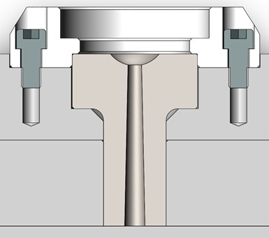
FIG 2 Straight sprue bushing.
The design in Fig. 2a should only be used for prototypes or extremely low production quantities. The design in Fig. 2 can be used for low- to medium-production quantities. Using a standard sprue bushing has two very serious design flaws. First, it requires the parting line opening between the runner stripper plate and the A-plate to be much longer, which can require a larger and more expensive molding machine with a greater opening stroke. Second, the cold sprue will more than likely hang up in the runner stripper plate, requiring it to be manually or robotically removed.
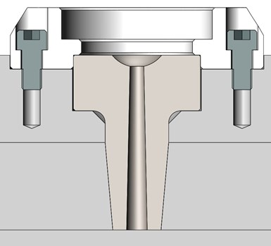
FIG 2a: Tapered sprue bushing.
The preferred design is to use a commercially available extended sprue bushing with a mating runner stripper plate bushing, as shown in Fig. 3. In my opinion, the standard sprue bushing shouldn’t even be an option for molders. All T-Series mold bases should be supplied with an extended sprue bushing and runner stripper plate bushing. They save material, potentially reduce the cycle time and eliminate the need for a much longer mold opening stroke.
Depending on the thickness of the runner stripper plate, you could have a minor issue that needs to be considered. Because the runner stripper plate bushing is only commercially available in 7/8 in. thickness, there’s a good chance of galling of the extended sprue bushing if the runner stripper plate is 1-3/8 in. or thicker, as shown in Fig. 4. This is easy enough to correct by adding a little clearance between the plate and the outside diameter of the extended sprue bushing.
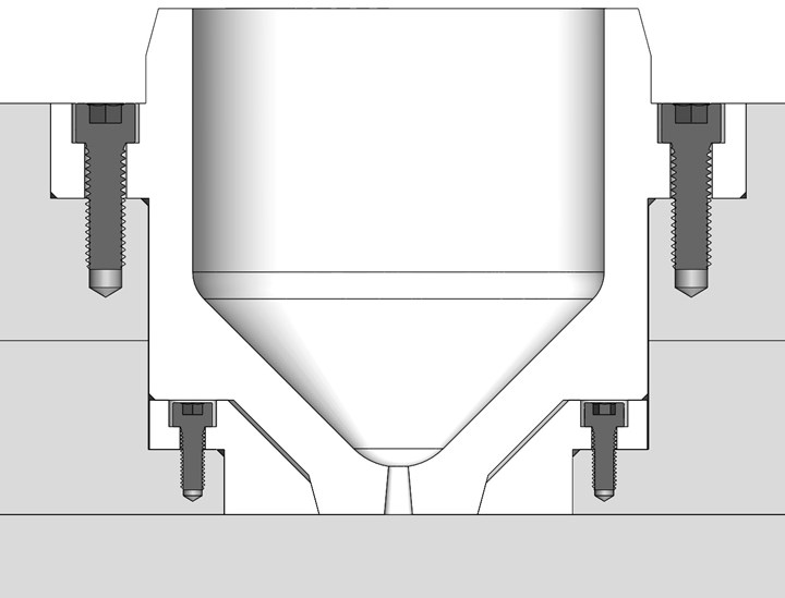
FIG 3 Extended sprue bushing and runner stripper-plate bushing.
If the mold design allows, I like to use the extended sprue bushings that have the larger 3-1/4 in. inside diameter, as shown on the right side of Fig. 5. You can run into issues on the production floor if the machine’s nozzle body with its attached heater bands and thermocouple can’t fit into the bushing without ripping the wires off. Note: The extended bushing with the larger recess may require a thicker injection clamp plate, which is often beneficial.
The cavities can usually be closer together in a three-plate mold.
While the dimensions for the extended sprue bushing and stripper plate bushing are very similar among mold component suppliers, their material types and hardness values vary widely. You would be wise to match the physical properties of these components with the intended life span of the mold. Softer components can wear out faster due to trapped dirt, debris and plastic flakes. They can also hob from flash on the runner, as well as nozzle drool and stringing.
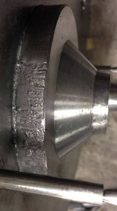
FIG 4 Galled extended sprue bushing.
The runner stripper plate bushing typically has an outside diameter of 2.750 in., but the tolerance is ± who knows what. If the fit of the bushing in the runner stripper plate isn’t a slip fit or tighter, it can result in down-flash, especially when the molding material is a low-viscosity resin, such as nylon. Down-flash can cause the runner to hang onto the runner stripper plate, instead of falling freely out of the mold.
What About the Runner?
There are only two acceptable types of runner types for a three-plate mold — trapezoidal and parabolic — as shown in Fig. 6. Parabolic is the preferred type because it uses slightly less material and will solidify slightly faster. It has slightly less cross-sectional area and the surface area is more uniform.
Other than having to be trapezoidal or parabolic, the runner in a three-plate mold has basically the same requirements as any type of runner in a two-plate mold. It should have a cold well opposite the extended sprue bushing the gate, as shown in Fig. 7. Granted, the cold well for a three-plate mold will have a much different shape than that of a two-plate, but it serves the same purpose: to catch any solidified material in the molding machine’s nozzle tip, preventing it from flowing down a runner channel and blocking a gate or leaving aesthetic marks on the part.
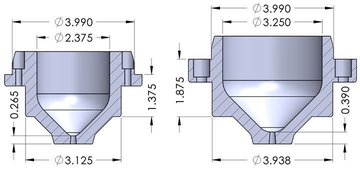
FIG 5 Small- and large-bore extended sprue bushings.
Despite most people’s belief, a runner overflow does not need to be added to the end of every runner branch. It has been proven that the cold well opposite a sprue bushing is so effective, one more overflow further down the melt flow channel, as shown in Fig. 8, is basically just insurance, because they also work extremely well. Any additional overflows will be a waste of material.
Three-plate molds need cold wells opposite the sprue.
Most people also believe you need to add a vent at the end of every runner branch. I am not sure I completely agree about adding vents to any portion of a runner system, no matter if it is a two-plate or three-plate mold. The purpose of a vent is to enable the air and gases to escape before entering the cavity. It seems logical to me that the air inside a runner system is going to take the path of least resistance and go through the relatively large gate orifice before it will go through a vent that’s only a thousandth or two deep.
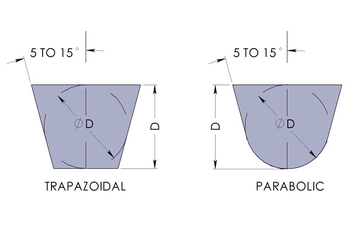
FIG 6 Acceptable three-plate mold-runner types.
The only scenario I can think of where venting the runner would be beneficial is when the gate(s) were very small and the injection velocity was extremely fast. In that scenario, it may be possible for a significant positive pressure to build up inside the runner system, which would force some of the air to escape through a vent before it is skinned over with material, preventing any additional air from escaping. It certainly can’t hurt to add vents to the runner, but I’d sure like to see someone write their thesis on it, backed with empirical data.
If the mold has multiple cavities of different parts, there is no reason why a runner turn-off (RTO) can’t be used, just like in a two-plate mold. In fact, it’s easier to install an RTO in a three-plate mold because you only need them on one side.
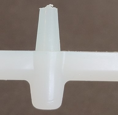
FIG 7 Three plate cold well opposite the sprue gate.
Obviously, the runner layout should always be geometrically or “naturally” balanced. Family molds can be extremely difficult to balance. The goal in balancing a family mold is to have all the parts finish filling at the same time — not necessarily start to fill at the same time. The primary reason why you want all of the parts to finish filling at the same time is so they all receive the same amount of packing pressure. If they don’t, you waste material by overpacking some cavities, which make them heavier.
Another reason is that cavities that are under-packed or overpacked will have dimensional issues because they will have a different shrinkage factor than what was used to machine the mold. The trick to adjusting a family mold is to adjust the flow rate of the material in the runners feeding each cavity. Changing the gate depth or width only changes the fill speed going through the gate. It does not change the volumetric flow rate (in.3/sec). Therefore, to correctly balance family molds, you need to change the runner flow area to each cavity.
There is an advantage to incorporating a runner bar in three-plate family molds.
I was taught decades ago that runners should be cut into a hardened insert, called a runner bar, especially if the material was abrasive. I was also taught that the runner should be highly polished to reduce the injection pressure. Fellow Plastics Technology columnist John Bozzelli showed me that because material flows like a fountain within the mold, there was no need for a hardened insert or a high polish.
However, there is an advantage to incorporating a runner bar in three-plate family molds. Because any required size adjustments to the runner need to be made, they can be made faster and easier with a removable insert instead of the entire plate. Additionally, the runner can be affordably made of a different material, such as a thermally-conductive material for faster cycle times.
Just like a two-plate mold, radiused runner turns are preferred over 90° bends, especially for shear-sensitive or glass-filled materials. If you do have any 90° bends, the inside corners should have their sharp edges blended to help reduce the stress on the material. It will also help prevent the runner from potentially cracking upon ejection.
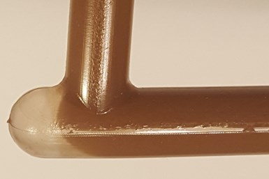
FIG 8 Cold wells are highly effective at trapping cold slugs.
Some runner layouts can have a heavy mass at branch intersections. These can often be cored out, just like you would with a two-plate mold, without affecting the material flow or pressure.
It may not be a bad idea to engrave the corresponding cavity numbers on the runner, as shown in Fig. 9. It makes it a little more foolproof when adjusting the runner flow areas. The engraving should be made in the A-plate. If it is engraved in the runner stripper plate, make sure there’s sufficient taper. Even a shallow engraving can cause the runner to hang up.
Invest in Flow Analysis
Three-plate molds often have longer cycle times than two-plate molds. This is due to the size of the runner. A flow analysis is a good investment for three-plate molds. Molders are often amazed at how small a runner can be made, as predicted by a flow analysis. A flow analysis can help minimize the amount of regrind and injection pressure loss, as well as the cycle time. If a mold flow analysis is not practical, the runners, drops and gates can be intentionally machined undersized. The pressure drop through the runner (and the gate) can be determined at the first sampling by conducting a scientific molding pressure loss study and the runners, drops and gates subsequently enlarged if necessary.
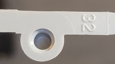
FIG 9 Cavity number engraved on the runner.
If the runner is to be extracted with a robot or a picker, you want the runner to be “free” but not fall out of the mold. You can add a molded pin in the runner stripper plate to hold the runner in position for the robot to grab, as shown in Fig. 10. The robot’s “strip-stroke” will pull the pin out of the runner stripper plate.
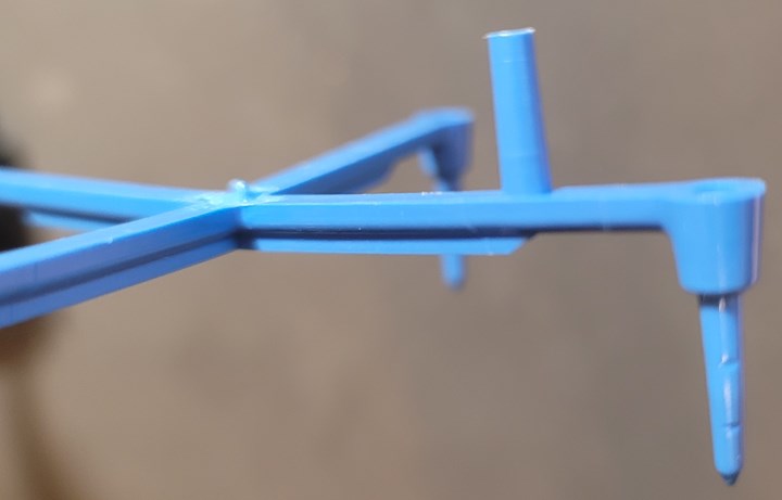
FIG 10 Three-plate runner with a molded pin for robotic extraction.
About the Author: Jim Fattori is a third-generation injection molder with more than 45 years of molding experience. He is the founder of Injection Mold Consulting LLC. Contact jim@injectionmoldconsulting.com; injectionmoldconsulting.com.
Related Content

Tunnel Gates for Mold Designers, Part 1
Of all the gate types, tunnel gates are the most misunderstood. Here’s what you need to know to choose the best design for your application.
Read More
Back to Basics on Mold Venting (Part 2: Shape, Dimensions, Details)
Here’s how to get the most out of your stationary mold vents.
Read More
Where and How to Vent Injection Molds: Part 3
Questioning several “rules of thumb” about venting injection molds.
Read More
How to Start a Hot-Runner Mold That Has No Tip Insulators
Here's a method to assist with efficient dark-to-light color changes on hot-runner systems that are hot-tipped.
Read MoreRead Next

Processor Turns to AI to Help Keep Machines Humming
At captive processor McConkey, a new generation of artificial intelligence models, highlighted by ChatGPT, is helping it wade through the shortage of skilled labor and keep its production lines churning out good parts.
Read More
How Polymer Melts in Single-Screw Extruders
Understanding how polymer melts in a single-screw extruder could help you optimize your screw design to eliminate defect-causing solid polymer fragments.
Read More
Troubleshooting Screw and Barrel Wear in Extrusion
Extruder screws and barrels will wear over time. If you are seeing a reduction in specific rate and higher discharge temperatures, wear is the likely culprit.
Read More