
How to Design Three-Plate Molds – Part 3
There are many things to consider, and paying attention to the details can help avoid machine downtime and higher maintenance costs — and keep the customer happy.


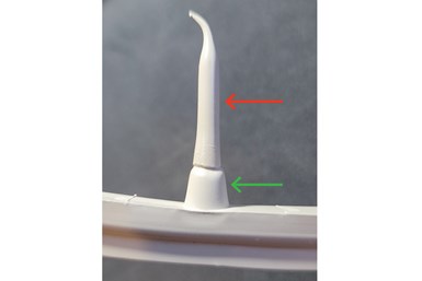
Fig 1: Machine nozzle tip cold slug
Photo Credit: Jim Fattori
One primary goal in any three-plate mold design is to minimize the length of all the parting line openings. Three-plate molds have a taller stack height and at least two additional parting lines. Therefore, they require a much longer opening stroke. It’s often necessary to put a three-plate mold into a higher tonnage molding machine only because a higher tonnage machine has the capability for a longer opening stroke.
But larger machines have a higher hourly rate and are often a little slower, which will cut into your profits. Larger machines usually have larger barrels, which could create a material residence time issue, as well as less control of the shot size, which can increase your reject rate. Other than increasing your machine utilization, there is absolutely no benefit to putting an injection mold in a machine larger than is required to fill the cavities and prevent flashing.


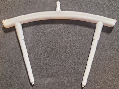
Figure 2: Curled three-plate runner
Photo Credit: Jim Fattori
When the machine’s clamp decompresses and starts to open, parting line #1A “breaks” a short distance (assuming you use urethane or compression springs). Then parting line Number 2 — which is the main parting line between the cavity and the core, or A and B-plates — usually starts to open. I say usually because on occasion the part may have a lot of surface area, low draft conditions, a textured surface and other factors (such as overpacking) that can cause the molded part to stick firmly in the cavity. So firmly, the parting line between the runner stripper plate and the A-plate continues to open before the cavity and core plates do. And that’s fine.
There are only two parting line opening sequences that really matter: (1) The initial break between the A-plate and the runner stripper plate must be first (as previously discussed); and (2) The parting line between the runner stripper plate and the injection clamp plate cannot start to open until the opening between the runner stripper plate and the A-plate is fully open. Otherwise, the runner may not have enough room to fall freely out of the mold.
The first opening must be between the A-plate and the runner stripper plate.
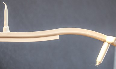
Figure 3A: Thin stiffening ribs help prevent bending and curling
Photo Credit: Jim Fattori
The amount parting line Number 2 needs to open depends on the molded part. It typically needs to be the height of the part, plus the height of the core above the parting line, plus some safe amount for the part to fall freely. Most parts tend to rotate when they are ejected. That rotation can be anywhere between zero degrees and 90 degrees, depending on the center of gravity of the part. The speed at which the molding machine ejects a part can also affect how it falls, as well as how much room is required. It’s a good idea to make this opening stroke a little longer than expected but have a simple method to possibly reduce that amount after the initial sampling, and potentially get you into a smaller molding machine, as well as a slightly reduced cycle time.
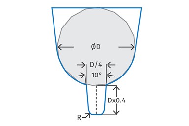
Figure 3B: Guideline for sizing stiffening ribs
Photo Credit: Jim Fattori
Once you have estimated what the total parting line Number 2 opening should be, that’s when some type of mechanism engages the A-plate and creates, what I call, parting line Number 1B — the full amount of opening between the A-plate and the runner stripper plate.
The amount the parting line between the A-plate and the runner stripper plate needs to be is typically equal to the combined distances of:
- The amount required to pull the entire length of the cold runner drop(s) out of the A-plate.
- The amount the runner stripper plate needs to advance to strip the runner off.
- The length of the short, solidified, sprue inside the extended sprue bushing, as indicated by the green arrow in Figure 1. This cold sprue length for a ½-inch spherical nozzle seat can range from 0.265 inch to 0.390 inch, depending on the inside diameter of the bore. The cold sprue length for a ¾ inch spherical nozzle seat can range from 0.265 inch to 0.453 inch, depending on the inside diameter of the bore. This is yet another of a long list of reasons why you should not be using machine nozzle tips with a ¾ inch radius.
- Whatever the possible length of any cold slug that is pulled out of the machine nozzle tip, as indicated by the red arrow in Figure 1.
- Some safe amount of additional clearance. There is a rule of thumb that says the open distance between the runner stripper plate and the A-plate should be 5 times the overall height of the runner system. That is a horrible rule of thumb and should be completely ignored. That rule is meant to overcome the common problem of the runner curling as it cools, but completely ignores all the reasons why a runner may or may not curl. It also ignores how cold and rigid or how hot and malleable the runner may or may not be. Nor does it consider if the runner is small and light or thick and heavy.
- There may be some additional clearance required if the runner is going to be removed by a robot or picker.
- That’s a long list of lengths to add up. This is when you double-check the maximum daylight and maximum opening stroke of the intended molding machine.
Regarding Number 5, the “safe amount” can vary a lot. If the material has a filler in it, such as glass or calcium carbonate, it tends to be rigid and usually will not bend or curl very much when it’s ejected. Unfilled materials and thick runners tend to curl a lot, especially when the runner is not completely solidified when the mold opens, as shown in Figure 2. This can require longer opening strokes for the runner to fall freely.
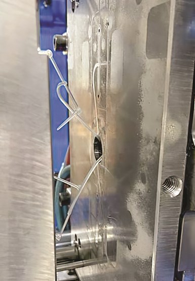
Figure 4A: A thin runner being retained by the molding machine’s nozzle tip
Photo Credit: Westfall Technik
It’s best to use a safe amount of opening, but make it easy to adjust after the first mold sampling. Even if the mold functions fine with the longer stroke — minimizing the amount of stroke afterward can shave a little time off the molding cycle.
It is important for processors to notice the direction the runner curled in Figure 2. It has nothing to do with the geometry of the runner; it is due to the mold cooling. Runners, as well as parts, will warp or curl toward the hotter sides or areas of a mold. Figure 2 is a good example of the runner stripper plate being colder than the A-plate, which is why it curled inward. The amount and direction a runner, or a part, warps can often be influenced by the temperature of the cooling lines in the various plates.
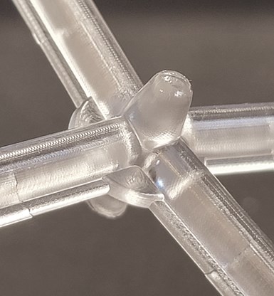
Figure 4B: Adding a center disk to the runner will help it eject
Photo Credit: Jim Fattori
To help prevent the amount a runner curls and reduce the required opening distance, a thin stiffening rib can be added as shown in Figure 3A. Figure 3B is a guideline for the size of a stiffening rib.
The runner stripper plate bushing has a 1¼-inch diameter opening in the center. If the cold slug in the machine’s nozzle tip has sufficient force to pull a flexible runner through this opening, as shown in Figure 4A, the runner will not eject. One method to help eliminate this problem is to add a center disc to the runner as shown in Figure 4B.
Flash traps on a runner will dramatically help reduce the amount of mold damage caused by flash, as shown in the before and after pictures in Figure 5.
When the molding material is injected into the mold, the flash trap fills and solidifies before the injection pressure starts to significantly build up. That’s what prevents the flash from extending beyond the flash trap. As a bonus, the flash trap helps prevent the runner from curling a little.
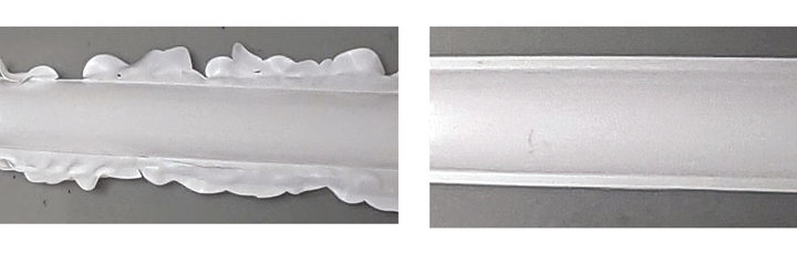
Figure 5: Flash traps on runners (left, before; right, after) prolong the life of a mold
Photo Credit: Jim Fattori
I like to make the flash trap depth and protruding width about 20% of the runner depth. For example, if the runner depth was ¼ inch, the flash trap would be 0.050 inchdeep and protrude 0.050 inch on either side of the runner. And, yes, flash traps are beneficial on all types of cold runner molds and all types of runner shapes.
Pulling Plates
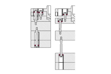
Figure 6: Range bolts used to control parting line openings. Left, closed. Right, open
Photo Credit: Jim Fattori
There are several methods that can be used to pull the various plates. The more common methods are range bolts, range bars, latch locks and plate locks. For small- to medium-size molds, I like to use range bolts. For larger molds, I like to use external range bars. I tend to avoid any mechanism that uses springs or has components that can wear or require grease. Range bolts and range bars can also have their stroke easily adjusted.
Figure 6 shows range bolts being used for all three parting line openings of a three-plate mold. Whatever method you choose, just make sure the components will not prevent the runner from falling freely out of the mold.
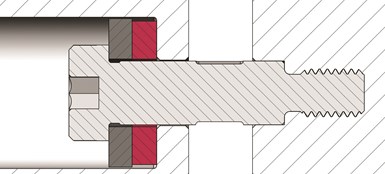
Figure 7: Close up of a range bolt
Photo Credit: Jim Fattori
Figure 7 shows some of the finer points about range bolts, such as how they should be mounted in a recessed or counterbored hole 1/32 inch to ¼ inch deep to help resist damage from any lateral loads. They should always have a thermoplastic washer, such as urethane, with a flat steel washer under their heads to absorb shock and dampen the noise. This shock absorption also helps prevent the threads of the bolt from stripping out. Often, the head of the range bolt is inaccessible for maintenance when the mold is in the press.
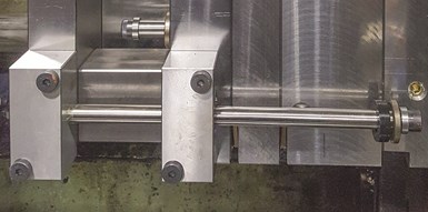
Figure 8: Range bolt mounted in a telescoping cylinder
Photo Credit: Jim Fattori
Machining opposing flats on the range bolt so that a wrench can be used to remove it can be very helpful. Hence the term “wrench flats.” For more detailed information on range bolts, see my June 2019 article.
Sometimes you can’t install a range bolt within a mold that is long enough to obtain the desired parting line opening. In a case like this, you can use a telescoping range bolt, such as in Figure 8. This design uses a standard range bolt mounted inside a floating cylinder. The cylinder has a shoulder on the end to limit the stroke of the assembly.
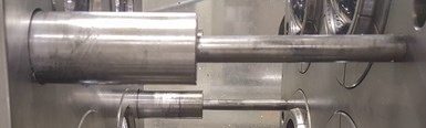
Figure 9: Range bolt mounted in a telescoping cylinder
Photo Credit: Jim Fattori
Other times you don’t have room to install all the range bolts within the mold base. In that case, you can mount a range bolt on the outside of the mold, such as in Figure 9.
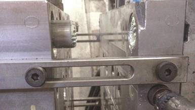
Figure 10: A basic range bar
Photo Credit: Jim Fattori
An alternative to range bolts are range bars, which are almost always mounted externally. They are a little noisier, unless you incorporate some type of snubbing feature, but they are very simple and effective. The most basic design is shown in Figure 10.
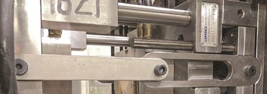
Figure 11: A telescoping range bar
Photo Credit: Jim Fattori
A telescoping design is shown in Figure 11. And a design for maximum opening strokes is shown in Figure 12. Notice how a spacer was added to one of the range bars in Figure 12 to reduce the opening stroke after the initial mold sampling.
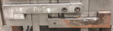
Figure 12: Range bars for very long opening strokes
Photo Credit: Jim Fattori
Figure 13 show an excellent method of achieving a parting line opening stroke that exceeds the stack height of the mold, without the use of the notorious metal chains. It’s the same premise as metal chains, but uses low-stretch, reinforced timing belts — the kind used on servo motors and motorcycles. They are extremely strong and have very high shock resistance.
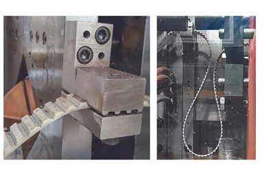
Figure 13: Timing belts used for pulling mold plates
Another benefit of timing belts is that the belt length, and corresponding opening stroke, can be adjusted in the press in a matter of minutes. I have had success with this little-known design, particularly on very large molds.
About the Author: Jim Fattori is a third-generation injection molder with more than 45 years of molding experience. He is the founder of Injection Mold Consulting LLC. Contact jim@injectionmoldconsulting.com; injectionmoldconsulting.com.


Related Content

Why Shoulder Bolts Are Too Important to Ignore (Part 2)
Follow these tips and tricks for a better design.
Read More
How to Mount an Injection Mold
Five industry pros with more than 200 years of combined molding experience provide step-by-step best practices on mounting a mold in a horizontal injection molding machine.
Read More
How to Optimize Pack & Hold Times for Hot-Runner & Valve-Gated Molds
Applying a scientific method to what is typically a trial-and-error process. Part 2 of 2.
Read More
Improve The Cooling Performance Of Your Molds
Need to figure out your mold-cooling energy requirements for the various polymers you run? What about sizing cooling circuits so they provide adequate cooling capacity? Learn the tricks of the trade here.
Read MoreRead Next

Processor Turns to AI to Help Keep Machines Humming
At captive processor McConkey, a new generation of artificial intelligence models, highlighted by ChatGPT, is helping it wade through the shortage of skilled labor and keep its production lines churning out good parts.
Read More
Troubleshooting Screw and Barrel Wear in Extrusion
Extruder screws and barrels will wear over time. If you are seeing a reduction in specific rate and higher discharge temperatures, wear is the likely culprit.
Read More