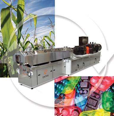
Biopolymer Compounding Done Right
Sponsored ContentBiodegradable polymers like PHA are set to slowly take over many areas of plastic production, but the material properties mean that special attention must be paid to the screw configuration and ventilation when compounding.
Share
Biodegradable polymers like PHA are expected to replace most single-use petroleum polymers over the next five years. However, these polymers often require special additives and fillers to meet product specifications.
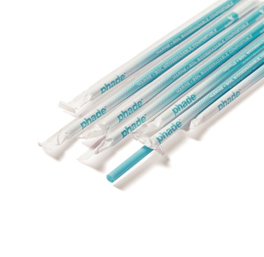
There is a huge push from governments and consumers to use Biodegradable Polymers with most of their attention focused on eliminating single-use petroleum-based polymers, for example straws, food packaging and grocery bags. Global Biopolymers such as PHA (Polyhydroxyalkanoate) are expected to drive this growth, and capacity is expected to more than triple over the next five years (September 2020 Compounding World article – Steady gains for bioplastic). PHAs are biodegradable, bio-based polyesters with quality physical and mechanical properties. For just one example, NodaxTM PHA from Danimer Scientific is experiencing significant growth and has been chosen by Bacardi (Hamilton, Bermuda) to replace 80 million PET (Polyethylene Terephthalate) bottles (3000 tons) currently produced by the company.
Biopolymers often do not meet required product property requirements in their pure form. Additives, fillers, impact modifiers, masterbatches and sometimes a portion of petroleum-based polymers are compounded into a biopolymer matrix to enhance product properties to meet product requirements and/or to reduce cost. A biopolymer product manufacturing life cycle typically includes a compounding step more than likely performed on a co-rotating TSE (Twin Screw Extruder).
Biopolymers absorb ambient water, which means they require cautious handling prior to processing (type of packaging, keeping containers closed or sealed when not in use).
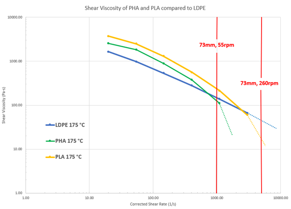
Biopolymers are shear sensitive resulting in viscosity and physical property degradation under high shear rate conditions provided by a co-rotating TSE. In the Shear Viscosity versus Shear Rate chart below provided by Danimer Scientific, the LDPE (Low Density Polyethylene) is nearly linear whereas the PLA (Polylactic Acid) and PHA lines have curvature, they cross over the LDPE line at higher shear rates indicating that the viscosity for these biopolymers drop off more rapidly at higher shear rates. The two vertical red lines on the chart tie extruder screw speed in rpm (revolutions per minute) and shear rate together specifically for a new ENTEK 73mm extruder:
How does the superior high shear mixing capability of a co-rotating TSE not destroy or degrade the biopolymer yet provide sufficient mixing to achieve the desired dispersion and/or distributive mixing of the fillers and/or additives compounded into the Biopolymer matrix?
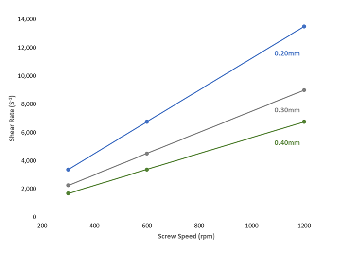
- The shear exposure of the material is directly proportional to the extruder screw speed. However, it is inversely proportional to the space between the barrel and the extruder screws. This means it is important to maintain a reasonable clearance between the top of the screw flight and the barrel. The larger this clearance the lower the shear rates as shown by the Shear Rate versus Screw Speed graph below for three discrete screw to barrel clearances of 0.20, 0.30 and 0.40mm.
- Below is an example of a shear rate calculation for the middle data point on the blue line in the graph above.

- Restrict the screw speed and operate the extruder at the lowest possible screw speed for a given throughput rate until either the extruder torque is too high (>90%) or a volumetric limit defined by compound backing up a feed opening or a vent. This achieves the highest specific throughput in Kilograms per hour per rpm (kph/rpm) which limits the shear rate, fills the extruder and makes best use of the conductional heat provided by the barrels.
- Configure the melting and mixing zones with narrow disc kneaders like the one circled red in the picture below because the mixing provided by these kneaders are less aggressive resulting in lower melt temperatures.
- Try to avoid using reverse convey screw elements when designing and building the screw configuration. Reverse convey screw elements pump the compound back towards the extruder feed throat resulting in more intensive mixing and increased residence time. Including reverse convey screw elements is sometimes unavoidable, for example, occasionally a set of reverse convey screw elements may be necessary slightly upstream of a vacuum vent to create a melt seal so that a vacuum can be drawn on the compound without sucking materials into the vacuum system.
- Avoid short aggressive mixing zones, by spreading out the mixing and/or melting zones to limit intensive shear mixing heat from the mixing screw elements and to maximize conductional heat imparted from the barrels into the compound. Long extruders, 48:1 L/D (Length/Diameter) or 52:1 L/D support this.

To effectively compound materials like biodegradable polymers, processors have to consider numerous factors such as the screw speed and the metalurgical properties of the extruder.
Fillers compounded into a Biopolymer matrix improve some of the physical properties and/or reduce cost of the biopolymer, but can present processing challenges. For example, talcum powder is a widely used polymer filler and is “fluffy” by nature because it drags a large amount of air into the extruder causing a volumetric limitation defined by compound backing up a feed opening or a vent, restricting throughput rates. Manufacturers can minimize the volumetric limitation by strategically placing vents for air to escape. This can also be achieved by placing restrictive types of kneading blocks or reverse screw elements as far as possible downstream from feed openings or vents. Relieving the air is critical to increasing rates and achieving as high as possible specific throughput.
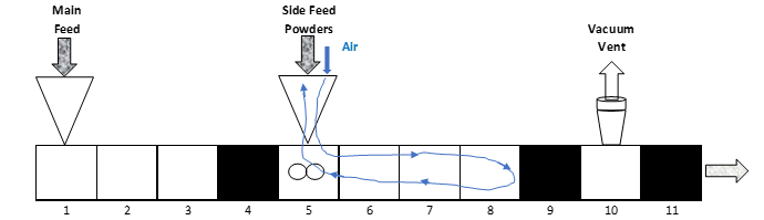
Below is a co-rotating TSE compounding system without air relief vents. In this example, the air flows back into the side feed port at barrel #5 creating turbulence, fluffing up the powder and restricting the flow of the powder into the extruder, limiting throughput rates:
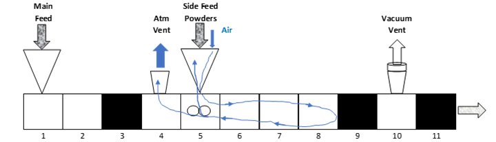
Below is a co-rotating TSE compounding system with an atmospheric vent at barrel #4, upstream of the side feeder, also known as a back vent for air relief. Some of the air moves out the extruder through the back vent and some of the air flows back into the side feed port. It is not uncommon to see back venting rate gains of 2 to 5 times compared to an extrusion system without air relief:
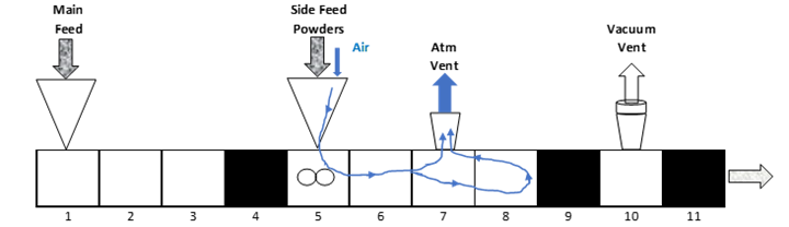
Below is a co-rotating TSE compounding system with an atmospheric vent at barrel #7, downstream of the side feeder at barrel #5, also known as a forward vent for air relief. The air moves out the extruder through the forward vent. Careful design of the extruder screw geometry inside barrel #6, allows for optimal air relief. If not designed correctly, excessive amounts of the filler powders discharge into the atmosphere at barrel #7 or insufficient air relief occurs at barrel #7 reducing potential throughput gains. (Forward venting can improve rates as much as 20 to 50% compared to back venting):
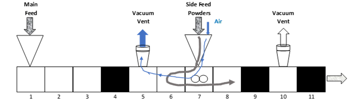
Below is a co-rotating TSE compounding system with a vacuum vent at barrel #5, upstream of the filler side feed at barrel #7. The air moves out the extruder from the Side Feeder at 7 through the vacuum at 5. Careful design of the screw geometry inside barrel #6, known as a filter zone, prevents the powders from being sucked into the vacuum system at 5. If not designed correctly, excessive amounts of the filler powders are sucked into the vacuum system at 5 or insufficient air removal occurs reducing potential throughput gains. This configuration is known as VFT (Vacuum Feed Technology) developed by ENTEK with a patent pending. (VFT can improve rates as much 20 to 80% versus forward venting):
Biopolymers are typically hygroscopic - They absorb ambient moisture to equilibrate at levels above 0.5% surface moisture. They require cautious handling prior to processing (type of packaging, keeping containers closed or sealed when not in use). It is effective to place an atmospheric vent early in the extrusion compounding process to minimize hydrolytic degradation of the molten biopolymer and to potentially avoid pre-drying of the materials. A vacuum vent is a required component, not a non-essential add-on. It is an integral part of the extrusion process and can often determine whether a system produces a quality product. A well-designed vacuum system – especially one that also addresses the often-corrosive nature of biopolymer volatiles – reduces maintenance and downtime along with increasing compounding rates. This pays for itself over time. Overall, the compounding extruder should include at least one atmospheric vent, possibly two; and at least one vacuum vent, possibly two. Vent stuffers can be used to achieve higher vacuum flow and higher vacuum pressures. The stuffer prevents the compound from escaping the extruder through the vent but allows the gases to escape.
ENTEK Extruders are designed to withstand the corrosive properties of molten biopolymers, and can be designed to use Vacuum Feed Technology. The HR73 is pictured above.
Pressure sensitivity of Biopolymers – While the co-rotating TSE is a superior mixing device, it is 5 to 15% efficient as a pump, which translates to a significantly increased melt temperature caused from a high extruder exit pressure. For example, in a co-rotating TSE running at 1,800kph of a filled Polypropylene, roughly 2.5°C melt temperature is added for every 10bar of back pressure at the screw tips. In other words, 60 bar die pressure will add 15°C. Furthermore, a high exit pressure can also cause vent flow at a vent located near the exit of the extruder. To address this problem, manufacturers can increase the diameter of die holes or the mesh size of filtration screens, or in the case of underwater pelletizing, increase water and die temperatures. These approaches can minimize extruder exit pressure to keep the melt temperature from rising significantly at the exit of the extruder. The most effective pumping elements are convey-screw elements with a pitch equal to one diameter. A Melt pump can be used between the exit of the extruder and the die, and they have pumping efficiencies of 25 to 35%. Using a melt pump minimizes the rise in melt temperature, conserves extruder power and creates a more stable flow extrudate. In cases where the extruder exit pressure is above around 60 bar, the cost of a melt pump can be justified by an increase in extruder throughput rates.
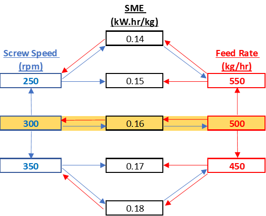
SME (Specific Mechanical Energy) - The single value for representing the cumulative compounding energy for melting, mixing, moisture removal, conveying and pressurization of the compound is SME. This is an easy metric to track the mechanical energy imparted to the compound from the extruder and is a good indicator of whether the shear energy is too excessive or insufficient. It is Power in kilowatts divided by throughput in kph:

Lowering the screw speed and/or raising the throughput rate of the feeders will reduce SME. Raising the screw speed and/or lowering the throughput rate of the feeders will increase SME. The diagram below is an example showing the influence of throughput rate and screw speed on SME:
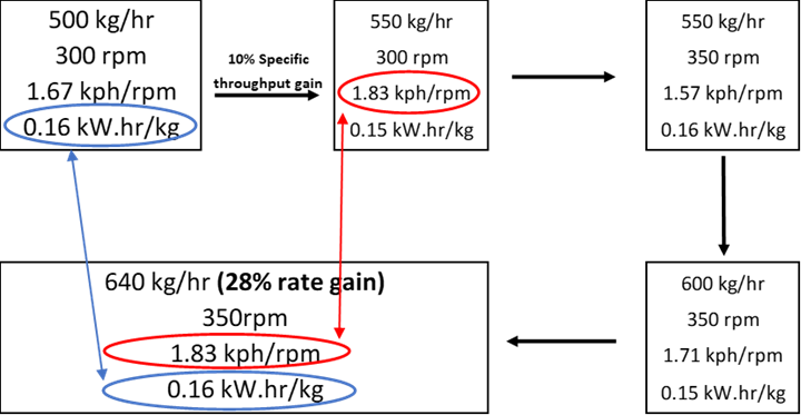
The example below shows how a 10% specific throughput gain leads to a 28% rate gain while keeping the same SME. Finding ways to increase specific throughput per this article will lead to higher throughputs while maintaining the same SME or product quality.
Biopolymers are heat sensitive – They degrade at elevated temperatures faster than their petroleum-based polymer counter parts. It is highly recommended to lower or turn off the barrel heats if the extruder will be standing for more than one or two hours. If the extruder heats are left on for long periods of time while the extruder is not running, purge the extruder with a low-cost, heat-stable polymer with a slightly higher melt viscosity. If the viscosity of the purge material is too high, it can show up as contamination for many hours after restarting production.
Extruder Metallurgy Choice - Molten biopolymers are corrosive and will attack screws and barrels causing premature wear. If abrasive fillers are being compounded with the Biopolymer, metallurgy that protects against abrasion and corrosion is necessary. Consult the extruder OEM (Original Equipment Manufacturer) when making screw and barrel choices. Extruder OEM’s will have a history of successes and failures, and can help with this important decision. Include adaptors, dies, screen changers, melt pumps, and other parts (any equipment that comes in contact with the molten compound) in the metallurgy discussion.
The design of the system should mitigate areas of stagnant polymer flow including maintenance of the screws and barrels which need to be tight fitting to prevent the heat sensitive molten biopolymer from entering any gap, stagnating and corrosively attacking the metal. When building screw assemblies, each element face needs to be cleaned and lapped to ensure that when screw tips are firmly tightened, the faces between the screw elements do not allow the biopolymer to enter. Initially, check and measure screws and barrels no less frequently than quarterly. These checking intervals can only be relaxed when a high level of confidence in the compound and metallurgy interaction is developed. Eventually move to a no less than bi-annual measurement regimen. Do not cut corners or save capital dollars, purchase the right metallurgy for the process. A catastrophic failure is extremely costly in both equipment and downtime.
ENTEK extruders are carefully designed with these material needs in mind, making them perfect for compounding biopolymers. For more informaiton, reach out to ENTEK.