
Getting into Plastics Additive Manufacturing? Avoid these Six Common Errors
There are a lot of 3D printing technologies out there, and it’s not uncommon for processors new to additive manufacturing to get tripped up. Here are some typical snafus, along with advice on how to avoid them before you start making parts.


Say you’re on a tight deadline to design and print a part that’s just right for your application. You’ve chosen 3D printing (aka additive manufacturing) to do the job because you know it allows for quick iterations, letting you tweak the part to your heart’s content. But the last thing you need is to get tripped up because you don’t have a solid knowledge of the technology you’re using. There are a lot of printing technologies available, so unfortunately, it happens.
Here are six of the biggest mistakes we see and some ways to fix them before you go to print.


1. Process Choice Affects Dimensional Accuracy
Let’s start with the issue we see the most. There are multiple 3D printing processes, and each delivers parts with different specs. While there are limited exceptions to some of the notes in this section, the most important thing to remember is that you should get to know the printing process first, before committing to it. Fortunately, the advancement of Industry 4.0 technologies has enabled automated design-for-additive-manufacturing (DfAM) to identify many of the most common issues as soon as you upload your CAD file.
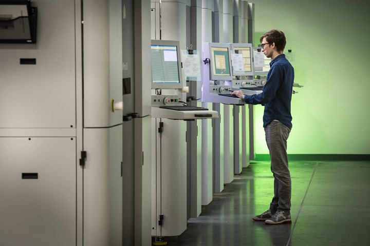
SLA printing is one option to consider when choosing a technology for additive manufacturing.
(Photo: Protolabs)
• Stereolithography (SLA): If dimensional accuracy and high surface quality are important, SLA will get you there, but it’s important to consider orientation to ensure proper feature formation. Knowing its limitations based on build orientation will help you better design parts for 3D printing.
SLA technology provides some of the best feature resolutions in the industry, but holes with diameters less than 0.020 in. (0.508 mm) could seal shut during the build. You should design internal channels to be at least 0.025 in. (0.635 mm) wide, and for slots, go with at least 0.015 in. (0.381 mm). There are specialized micro-resolution materials that allow holes less than 0.020 in. (0.5 mm), or slots less than 0.015 in. (0.381 mm), but not all manufacturers stock them.
Get to know the printing process first, before committing to it.
Be aware that you can only get the thinnest features in the draw plane (x, y), as opposed to the build plane (z). Think carefully about features such as support walls, inset, and embossed features (as on 3D-printed micromolds). Keep in mind that thin features that are longer or taller must be designed thicker to maintain strength.
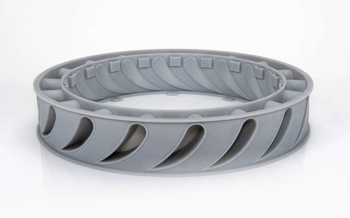
Parts made through SLA using thermoplastic-like materials are an excellent choice for prototyping but lack strength and durability, so choose your material carefully. (Photo: Protolabs)
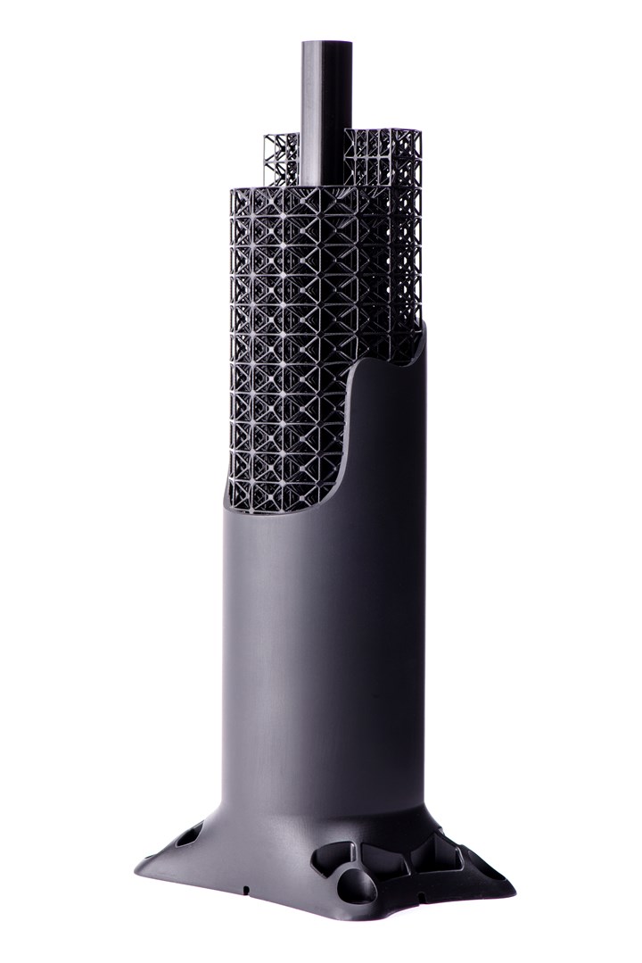
• Carbon DLS: The Carbon DLS (digital light synthesis) process uses light to solidify UV-curable resin into durable parts. It’s good for complex designs with isotropic qualities (equal strength in all directions). When designing parts for this process, you should avoid overly thick walls, but they must be at least 0.040 in. (1.016 mm) thick. Anything less will result in features not fully forming or severely warping. Watch out, though: Since these walls are fairly thin, they can easily break in post-processing.
On the opposite end, we sometimes see walls that are too thick, which can result in stress-cracking or dimensional inaccuracy. It is important to try to keep most walls in the 0.040-in. to 0.125-in. (1-mm to 3.16-mm) range.
With SLA, thin features that are longer or taller must be designed thicker to maintain strength.
While structural walls need to be at least 0.040 in. (1.016 mm) thick, Carbon has excellent positive feature resolution — features defined by solidified resin. The minimum positive feature size is 0.020 in. (0.508 mm). This applies to features like small text and inset or embossed elements.
For negative spaces, we suggest that the minimum hole, channel or gap size be at least 0.025 in. (0.635 mm) because the resin is quite viscous — anything less would risk having the feature seal shut during the build.
• SLS, MJF with nylons: When printing with nylons using selective laser sintering (SLS) or Multi Jet Fusion (MJF), there are three important issues that need to be addressed in your CAD model. Common geometries that might be problematic include blind holes, threads and areas where internal diameters and tapers are near exterior walls.
a. Wall thickness: This refers to the thickness of part walls or geometries in any direction. The minimum allowable wall thickness is 0.030 in. (0.762 mm) in SLS and 0.020 in. (0.508 mm) in MJF.
b. Channel gaps: This refers to the distance between two features. Get too close and you’ll have issues during the build. Because the sintering process can fuse two features together in locations that are close together, it’s important to include channel gaps. We recommend minimum channel gaps of 0.030 in. (0.762 mm) for both SLS and MJF.
c. Knife-edging: Although you typically want to avoid these very thin features in your designs, sometimes you need them, so you want to design them correctly. For example, think of a counter-bored hole. Your dimension may drop below the minimum feature size at the distal end of the hole. This could result in a shortened or round feature that does not form properly.
2. Avoid Low-Resolution STL Files
If you send your customer low-resolution STL files, you’ll end up with parts with coarse faceting (surfaces like a gemstone). The parts will still be manufacturable but might not be desirable aesthetically. To avoid this issue, adjust your STL resolution in your export settings. Note that reducing angle tolerance usually has the greatest effect and improves resolution.
We recommend high-resolution STLs that are still small enough to be uploaded and manipulated (100 MB or less). Even better: submit a STP/STEP file and your manufacturer will likely convert it to STL on their end.
3. Preventing Warpage in SLS and MJF Parts
Put enough heat on certain plastics and they’re likely to sag. Powder-based printing processes like SLS and MJF use heat to sinter powder together into a solid part, but the same heat that melds the layers together can also cause them to warp. It’s all about part size and overall thickness. The bigger the part — 7 in. (177.8 mm) and larger is particularly difficult — the more likely the part is to warp. Also, thin parts with small feature sizes are more likely to warp. So, what can you do about it in your designs?
• Aim for uniform thickness of 0.080 to 0.125 in. (2.00 to 3.175 mm) to help ensure stability.
• Consider using glass-filled or mineral-filled nylon SLS materials, like nylon 12 with 40% glass or 25% mineral filler. These strengthen the part while lessening warpage.
• If your part is larger than 7 in. (177.8 mm), and you are concerned about warpage, consider other printing options than MJF, such as SLS or SLA.
4. Avoiding Inconsistent Shrink in SLS, MJF
Shrinkage can be a problem, too, especially when there is unequal distribution of material across the breadth of the part. It’s all about cooling. Thicker areas of parts will cool and coalesce more slowly, and this can lead to undesirable part shrinkage.
Put enough heat on certain plastics and they’re likely to sag.
If a thick feature is required on a part, consider hollowing the feature to a shell of approximately 0.100 to 0.125 in. (2.54 to 3.175 mm). If possible, match the overall thickness of your part to the large feature’s shell thickness.
5. Carefully Choose Material for SLA Parts
Today’s SLA machines use a range of thermoplastic-like materials, some of which can mimic popular and strong resins like PP, ABS and PC. But it’s important to remember that these are thermoplastic-like analogues of popular thermoplastics, and can only emulate the properties of their molded counterparts. Generally, SLA parts are not as strong or durable as parts that are sintered, cast, machined or molded. Nevertheless, SLA is still an excellent choice to prototype parts that can validate form and fit — but not necessarily function.
For the different printing technologies, there are limitations around materials available, maximum part size, minimum feature size and tolerances. (Source: Protolabs)
6. Designing Elastomeric Parts for Overmolding
Overmolding elastomers is tricky when it comes to 3D printing. One process, PolyJet, can use a special “sprayable” liquid photopolymer that allows you to adjust hardness as the part is built. That’s helpful if your aim is to prototype parts that will at some point be overmolded — such as a soft, grippable handle for a power tool or a weatherproof, gasketed cover for a scientific instrument housing.
If you want to validate an overmold design, PolyJet is probably a good place to start. However, you need to ensure that your design is suitable for molding. Some designers get married to particular geometries, only to find out too late that the part can’t be manufactured cost-effectively in large quantities.
ABOUT THE AUTHOR: Eric Utley is technical sales engineer for 3D Printing at Protolabs. With more than 12 years of experience in additive manufacturing, he provides consultative guidance to engineers on designing for manufacturability for applications in medical, consumer products, aerospace, and automotive industries. Contact: eric.utley@protolabs.com; protolabs.com.


Related Content

Large-Format “Cold” 3D Printing With Polypropylene and Polyethylene
Israeli startup Largix has developed a production solution that can 3D print PP and PE without melting them. Its first test? Custom tanks for chemical storage.
Read More
Medical Manufacturer Innovates with Additive Manufacturing and Extrusion Technology Hubs
Spectrum Plastics Group offers customers two technology hubs — one for extrusion, the other for additive manufacturing — to help bring ground-breaking products to market faster.
Read More
3D Printing of Injection Molds Flows in a New Direction
Hybrids of additive manufacturing and CNC machining can shorten tooling turnaround times.
Read More
Freeform Injection Molding Eases the Path to Medical Device Product Testing
A development and manufacturing service provider is using dissolvable molds to build injection molded silicone prototypes.
Read MoreRead Next

Manufacturability Analysis for 3D Printing Designs
Protolabs has added a design for additive manufacturability (DfAM) analysis for 3D-printed parts to its online quoting platform, allowing users to optimize designs prior to printing.
Read More
“Injection Molding at the Speed of 3D Printing”
Wait—isn’t that backwards?
Read More
Protolabs CEO Discusses the Digital Age of Manufacturing
As the company reaches its 20-year milestone, Plastics Technology talked with Protolabs CEO Vicki Holt about what’s next for the innovative company.
Read More