Sequential Valve Gating
Ultimate Control for the Toughest Molding Jobs
Parts consolidation in automotive and other applications is creating larger parts with more complex geometries. These parts tend to be harder to fill and susceptible to problems of overpacking, warpage, and flashing. At the same time, these large, complex parts have to meet stricter surface-quality requirements. Demand is also rising for family molds of different-sized parts, for parts that combine different materials, and for greater flow lengths in thin-wall parts.
Conventional valve-gated hot-runner systems are having a tough time handling these challenges. Opening and closing all the valve gates at the same time necessarily limits the degree of control over weld or knit lines, gas traps, localized packing, and unbalanced flow. Fortunately, there is a technique that provides almost unlimited control over which parts of a tool fill when and how fast. It’s called sequential valve gating, or SVG. Adding a programmed time sequence to the opening and closing of valve gates is not new technology, but molders are gradually gaining appreciation of its problem-solving prowess.
Take, for example, family tools that have a complex geometry in one cavity and simple dimensions in another, or a multi-gated part that is asymmetrical or has thick and thin areas or ribs, bosses, or living hinges. “These circumstances can invite problems during molding,” warns Bruce Casey, general manager of Plastic Engineering & Technical Services (P.E.T.S.), a supplier of hot-runner systems. In such cases, molders with conventional valve-gate systems may have to overpack some areas of the part in order to completely fill out other areas. These overpacked areas not only waste material but are also vulnerable to problems of sticking, warpage, and frozen-in stresses, adds Ken Kurtz, hot-runner product manager for D-M-E.
In subsequent painting operations, part stresses can create problems with splay or paint adhesion. Furthermore, the overpacking could demand the use of a more robust press with a larger injection unit and increased clamping requirements.
Simultaneous filling from multiple gates can also be a problem with other decorative processes such as in-mold lamination (or back molding). Textiles or films inserted in the tool may fold or ripple if the filling process is unbalanced.
For multi-gated single-cavity parts, the position and appearance of weld lines is becoming increasingly important. Occurrence of a weld line in a critical high-stress area can compromise the integrity and performance of the part, says John Blundy, Incoe’s v.p. of business development. Multiple gates can also produce weld lines that remain visible even after painting.
“A knit line in a colored part will result in glaring visual-effect problems, while a knit through a glass-filled part would have a negative effect on both the aesthetics and the performance,” agrees Kurt Weiss, manager of part performance and new material introductions at GE Plastics.
Many solutions have been tried, including the costly one of controlling fill by adding sliders to the mold, Kurtz notes. “Some molders may have tried to control the fill pattern by restricting nozzle bores and gates in order to reduce overpacking, stress, or weld- line issues, but that can lead to excessive melt shear at that smaller orifice,” says Harald Schmidt, president of Mold HotRunner Solutions (MHS). “This idea may be good when molding the same part with the same wall thickness, but bore balancing locks you into a narrow processing window for other jobs,” he adds. “You cannot change the viscosity of the material, the pressures, or the temperature. With SVG, the molder gains control over the cavity fill pattern to produce quality parts even when the material or the conditions change.”
A somewhat better approach may be to adjust runner sizes rather than gate sizes to shift weld-line locations, says Murali Anna reddy, product line manager at Moldflow, the mold-simulation software provider. “This method of artificially balancing the flow is quite popular with family molds. Moldflow provides an automatic flow-balancing program that sizes the runners. However, this might result in differing amounts of shear experienced by the melt, which could affect part quality.” Freeze-off is another risk in the smaller runners, Annareddy warns. “And an artificially balanced feed system is typically more sensitive to changes in the process settings.”
In the past, difficulties such as these forced some molders to rule out the use of multiple gates or more than a few cavities in high-precision applications because uniform, tight part tolerances were simply too hard to achieve.
What SVG brings
After 10 years of commercial availability, SVG is gaining favor as an alternative to traditional valve gating and thermal gating methods. Some of the delay may be due to the long lead times for automotive projects. But SVG is proving its unprecedented ability to control knit lines, which can be moved to a non-critical area, or even out to a vent. Sequencing of the valves also provides a way to fill family molds uniformly and to eliminate overpacking and flashing. Similarly, a bad cavity in a multi-cavity mold can be blocked off without throwing the whole tool out of balance. “A molder can achieve balanced fill using the gates instead of through runner and manifold sizing,” says Neil Dewar, product engineer at Mold-Masters.
Suppliers cite other benefits, too: Progressive fill through a few gates at a time can reduce clamp-tonnage requirements by 20% to 30% as compared with filling through all gates at once. Pack and hold can be profiled with greater precision, supplying longer or more intense packing to just those areas that need it.
At least eight suppliers of hot-runner technology offer SVG technology. They include D-M-E, Incoe, Husky, MHS, Mold-Masters, Osco Systems, P.E.T.S., and Synventive. These firms say they have installed from dozens to hundreds of SVG systems.
Automotive is the major market focus for SVG, especially for large parts like bumpers, fenders, wheel liners, rocker panels, grilles, fans, radiators, air-intake systems and instrument panels. Optical parts like lenses are also a target. SVG is also opening the doors for valve gating in leading-edge automotive applications like in-mold lamination, film-insert decorating, coinjection, hard-soft multi-material molding, gas assist, and long-glass composites. Mark Moss, Synventive’s senior v.p. of sales, marketing, and R&D, cites one example: “Coinjection of TPO automotive bumpers is not a big market right now, but it is being run successfully.” Sequentially molding a TPO bumper with a virgin skin and recycled core could help auto makers meet coming requirements for “green” vehicles. A part like that wouldn’t be moldable with a standard valve-gate system, according to Moss.
Incoe also worked on SVG for coinjection three to four years ago with Bemis Manufacturing Co., Sheboygan Falls, Wis. Coinjection was used to capture a dissimilar material in the core.
Automotive molders have a big cost incentive to get away from painting. Suppliers believe SVG will be important to the growth of decorative film insert molding as a replacement for painted exterior parts such as door panels.
Osco Systems, which claims to have invented the SVG technique, first applied it to solving cosmetic problems in auto parts. “At least 10 years ago, we worked on dozens of molds for truck and car grilles for GM and encountered knit-line problems. We used SVG to move the lines from plain sight out to a bezel,” says Osco sales v.p. Peter Rebholz. “About the same time, we started to work with in-mold decoration, where SVG could roll the plastic into the mold and not degrade or blow over the insert appliqué. We also started using SVG with family molds, making a packaging lid and container in one mold,” says Rebholz.
“We’ve seen SVG applications going back 10 to 15 years for items such as back housings for televisions. It allowed the molder to produce acceptable large parts that didn’t need painting,” says Mold-Masters’ Dewar. “We’ve also seen applications done with 30% glass-filled nylon for an automotive under-hood application. Weld lines would have deformed the part surface and affected the part from a structural point of view.”
Collins & Aikman of Troy, Mich., is using SVG for a challenging in-mold lamination project, says Mark Nietzke, program manager for interior trim development. “The SVG system is employed to control the filling pattern in the tool and also to help lower the pressure that the foam-backed vinyl insert would see in the injection phase.” The 16 x 20 in. polypropylene part is produced with an SVG system from P.E.T.S. in a joint venture with molder Engineered Plastics Products of Owasso, Mich. Previously, these parts were injection molded and then hand wrapped with the foam/vinyl covering. Nietzke says Collins & Aikman will shortly launch another SVG project, this one a vinyl-covered door panel for GM’s Epsilon car. Three of four molds for the project are already built and being validated for the process. An SVG fabric-covered instrument panel is being considered for the model 2006-07 year, he adds. Collins & Aikman also has in development an SVG seat back for Visteon.
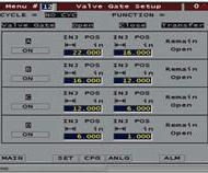
One of the most high profile SVG parts is a two-component weather strip for the Ford F150 pickup truck. The first shot is a 20% talc-filled PP. The second shot, produced in a rotating mold on one machine, is a soft Santoprene TPV with a silicone additive for lubrication. Innatech of Rochester, Mich., a custom injection molder specializing in multi-shot operations, expects to mold up to 1.4 million of these parts per year. The thin, 38-in.-long weather strip, which goes between the front and rear side doors is a combination sound damper, weather seal, and cosmetic close-out, says Jack Elder, advanced development manager. SVG is used only on the TPV edge seal. Five gates are used to fill gradually from the center in order to erase gate blemishes, knit lines, and gas traps, says Elder. All gates are set at angles of 30° to 45°to avoid gate blemishes. The SVG system comes from Incoe, but Innatech designed its own PLC control system for the process. This system allows discrete on/off control of each valve gate multiple times within the injection cycle, based on a screw-position signal from the press. The part was a finalist in this year’s SPE Automotive Plastics Innovation Awards.
Cosmetic enhancement is a major reason for using SVG, but not the only one. Husky has used SVG to reduce clamp tonnage by nearly 30% on a 1500-mm-long fascia impact absorber, reports product manager Kevin Golden. “Our components are used to do a lot of automotive grilles. Most large-nozzle systems are being done with SVG.” Husky has built SVG systems for parts weighing as much as 80 lb.
As far back as 1995, Nascote Industries, Nashville, Ill., a leading large-part automotive processor and early adapter of SVG, dropped cycle time from 110 sec to under 75 sec to mold a bumper from GE’s Xenoy PC/polyester resin. Most of the savings came from reduced clamp-force requirements. The firm also said faster cycles with SVG allowed it to increase capacity without additional presses. It also provided relief from splay and paint-adhesion problems.
MHS and German partner MHT recently cooperated in building several large automotive SVG hot halves with 6000-lb plates for Decoma’s plant in Germany. MHS’s Schmidt sees SVG opening the door to multi-cavity tools for large thin-wall parts. “In the future we will see TPO bumper fascias with 2-mm wall thickness or less,” he says. “The thinner wall will contribute to a shorter cooling time, but this will increase the flow resistance of the melt. More severe weld lines will be due to a higher pressure drop and a faster cold-layer formation. But SVG prevents these problems in large thin-wall parts.”
There are plenty of non-automotive markets for SVG, too. “We’ve done sequentially gated parts that fit in the palm of your hand,” says Osco’s Rebholz. GE Plastics developed a notebook computer case with only a 1-mm wall that was filled sequentially through 11 gates. “We wanted to push the envelope,” says Greg Tremblay, senior process engineer. GE developed a carbon-filled conductive compound of its Lexan polycarbonate that “flows like dried mud,” Tremblay says. It would not fill correctly with a conventional valve-gated system. Using SVG, they were able to fill the part in less than 1.5 sec.
Several roads to SVG
The majority of SVG systems in the field typically use from four to 12 drops, but some have as few as two gates and as many as 24. Casey of P.E.T.S. says on average an SVG system costs about 15% to 20% more than a standard valve-gate system, mainly for the extra control capability.
SVG can be divided into two main applications that have somewhat different mold-filling aims. One SVG approach is suited to multi-cavity molds like family tools. It seeks to achieve balanced filling without overpacking. The other is so-called “cascade” molding, which is generally applied to long or large parts for improving part finish, says D-M-E’s Bob Starr, manager of marketing services.
Cascade molding is designed to emulate the single melt-flow front and lack of weld lines obtained when only one gate is used. A cascade design positions the gates so that the melt flow length from one nozzle ends just past the gate of the next nozzle. When the melt passes a nozzle, that nozzle is opened. The new melt comes in behind the preceding flow front. Hot melt from the new nozzle “rejuvenates” the melt front ahead without forming a weld line.
The cascade can be designed to flow from the center of part out to both sides or from one end of a part to the other. A third approach may be to open the gates on both outer part edges and bring the two melt streams together at the center of the part. In either case, “the objective is to keep the melt flow moving before it sets up,” says Osco’s Rebholz. Setting different temperatures at each gate tip may assist in this goal.
The distance the melt front travels from one gate to another and the timing of opening and closing gates are critical parameters in SVG. “If you open the second gate too early you will get backflow and all sorts of nasty consequences,” warns Innatech’s Elder. “If you open the gate too late, the material from the first gate will be solidified at the surface. In either case you won’t reap the benefits of sequential valve gating.” Backflow can occur because the material approaching the second gate is cooling and losing pressure, while material fresh from the new gate is hot and under more pressure.
Gate opening can be triggered by time, screw position, or a pressure transducer in the cavity. Proximity switches that provide feedback on the valve gate’s pin position can be useful as a safety check.
Proper venting is always important in SVG, advises Casey of P.E.T.S. “If the mold is not vented properly, air between two melt flows can be trapped in the tool.”
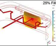
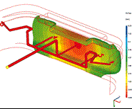
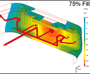
Due to the number of complexities involved in SVG, many hot-runner suppliers advocate use of computer flow simulation when designing the mold. Moldflow has been involved in SVG simulation for several years. Weld lines are a particular focus for users of SVG flow simulation. “There is currently no way for simulation to predict the actual strength of the weld, so the best one can do is look at the predicted temperature and pressure at which the weld line is created. In general, weld lines created at high temperatures and pressures will be stronger. We can then time the opening and closing of the gate to minimize or eliminate those weld lines,” says Moldflow’s Annareddy.
Even SVG may not provide adequate local control of filling and packing pressure in large, complex parts. In such cases, Synventive says its Dynamic Feed SVG technology picks up where standard SVG leaves off. Unlike typical valve gates, which are either fully open or fully closed, DF nozzles can be opened or closed to varying degrees, changing the effective size of the flow orifice. DF thus provides real-time filling and packing control at each individual gate. “What Dynamic Feed amounts to is a dimmer switch,” says Synventive’s Moss.
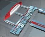
Introduced as far back as 1998, the closed-loop DF system has a hydraulic cylinder that moves a special flow-control pin in the nozzle. A pressure transducer in the hot runner sends a signal to the controller, which compares the actual pressure to a set pressure profile. The controller operates a servo valve that controls the movements of the hydraulic cylinder. Whereas conventional injection molding uses velocity control during the filling stage and then switches over to pressure control for final filling and packing, DF uses pressure control only. DF is said to provide the most accurate control over packing, since pressure is sensed right at the gate.
Says Moldflow’s Annareddy, “With this control, you are no longer restricted to ensuring that all the cavities fill at the same time.” Moldflow and Synventive are working together on DF mold simulation.
Tier-one automotive supplier Lear Corp., Southfield, Mich., has used DF to make numerous interior A-, B-, and C-pillars as well as HVAC doors, bumpers, wheel-arc liners, and a three-part overmolded cluster bezel. Other molders have used DF to mold interlocking bracket supports, precision ink-jet cartridges, and stud sensor assemblies. One thin-wall, multi-cavity project produces mobile-phone front and back covers in a four-gate mold. Mikron Mould Technology in Faareveje, Denmark, produces the PC/ABS parts with an injection time of 0.4 sec. The housings have a wall thickness from 0.7 to 1.5 mm. Total cycle time is 13 sec for the parts, which require a shot weight of 8.85 g.
While not revealing details, P.E.T.S. is planning to roll out a new valve-pin design for SVG during the first quarter of 2004 that “does more than open or close all of the way when actuated,” says Casey.
Related Content
Slimmer All-Electric Press Debuts
A slimmed-down version of Engel’s all-electric, e-mac injection molding machine is among eight displays, which also include LSR micromolding, quick mold changes and a cube mold.
Read More50 Years of Headlines … Almost
I was lucky to get an early look at many of the past half-century’s exciting developments in plastics. Here’s a selection.
Read MoreWord Games: What’s a ‘Hybrid’?
Any molder will tell you there’s a difference in working with electric vs. hydraulic drives. Servohydraulic is still hydraulic; a hybrid machine is something different. Imprecise use of terms causes needless confusion.
Read MoreInjection Compression Molding as Alternative to Thermoforming
Arburg will show its all-electric Allrounder 720 A press utilizing injection compression molding to create thin-wall IML cups from PP.
Read MoreRead Next
Lead the Conversation, Change the Conversation
Coverage of single-use plastics can be both misleading and demoralizing. Here are 10 tips for changing the perception of the plastics industry at your company and in your community.
Read MoreAdvanced Recycling: Beyond Pyrolysis
Consumer-product brand owners increasingly see advanced chemical recycling as a necessary complement to mechanical recycling if they are to meet ambitious goals for a circular economy in the next decade. Dozens of technology providers are developing new technologies to overcome the limitations of existing pyrolysis methods and to commercialize various alternative approaches to chemical recycling of plastics.
Read More



%20system.jpg;width=860)






.png;maxWidth=300;quality=90)
