
How to Get Better MFI Results
The MFI test is used widely among the various segments of the plastics industry. The difficulty is that any two labs can easily come up with different results, making it difficult to determine whether a material meets a desired MFI spec. Here are some reasons why such discrepancies occur and what can be done about them.
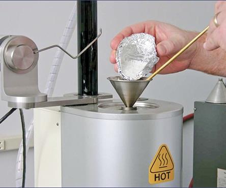
It’s good practice to control the sample charge size based on the expected flow rate.
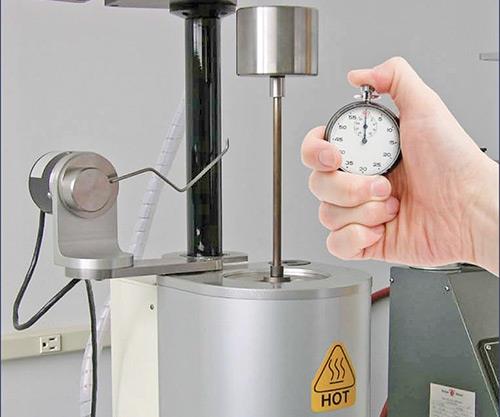
ASTM specifies 420 ± 30 sec of preheat time for most materials.
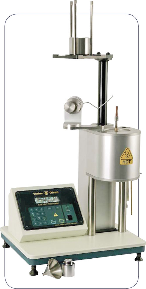
This melt plastometer from Tinius Olsen combines an automatic timing switch and a motorized weight-support/lowering and lifting device for automated tests.


The melt flow index (MFI), also known as the melt flow rate (MFR), determines the melt flow properties (measured in g/10 min) of a material at a specific shear stress (related to applied load) and temperature. An extrusion plastometer, more commonly referred to as a melt indexer, is used to determine the MFI of virgin, compounded, and post-processed thermoplastics.
The MFI test is used widely among the various segments of the plastics industry. Resin suppliers, for example, look for MFI variations as a QC check to detect and troubleshoot variations in their polymerization and/or compounding processes. As part of their materials-inspection procedures, some processors use the test to determine the amounts of recycled material that can be used in their product while still maintaining end-product specifications. The difficulty is that any two labs can easily come up with different results, making it difficult to determine whether a material meets a desired MFI spec. Here are some reasons why such discrepancies occur and what can be done about them.


KNOW YOUR STANDARDS
There are two major MFI test standards:
•ASTM D1238: Standard Test Method for Melt Flow Rates of Thermoplastics by Extrusion Plastometer,
•ISO1133: Determination of the Melt Mass-Flow Rate (MFR) and Melt Volume-Flow Rate (MVR) of Thermoplastics.
Both measure the same property, but slight procedural and equipment differences can yield different results. Both offer a manual means (Procedure A or Method A) and automatic timed-flow measurement (Procedure B or Method B). In theory, both methods, if properly performed, will yield identical test results.
There is really no consensus as to which method is best; however there are some guidelines that can be used to make a choice. Procedure A is typically most useful for companies that test infrequently, use a wide range of materials, use a variety of additives in their materials, or use regrind/recycled material. Procedure B requires a “melt density” value and is best for companies that test the same material repeatedly and want to minimize the chance of operator error. Others may find that the alternative Melt Volume Flow Rate (MVR) procedure, offered by both standards, is more useful.
No matter what the procedure selected, it is common for two organizations to test the same material and come up with two different test results, setting off a search to determine the reason for the difference. A variety of factors affect the precision and accuracy of a test. Is the melt indexer in good working order? Has the machine been calibrated by a certified metrologist—checking temperature, physical dimensions, and distance- and time-measurement accuracy? Is the machine clean? Are the operators properly trained and using the same testing technique?
The chances of obtaining precise and accurate test results can be greatly increased by closely following proper testing procedures and requirements, by machine verification, and by periodic testing of control materials or a standard reference material (SRM). Even so, “bad” or variable MFR results attributable to the equipment and/or procedures can still be encountered. Examining the actual industry test standards offers direction here. ASTM D1238 offers a Troubleshooting Guide in the Appendix of the document and the following thoughts are based upon it. (Consult ISO 1133 for appropriate dimensions and procedures when testing to that standard.)
Some labs do use a Standard Reference Material (SRM) to crosscheck MFI test results. There is a limited supply of selected materials available from national metrological standards bureaus (including NIST in the U.S.) but they tend to be expensive and can only help verify testing for that particular material. Some labs maintain their own supply of reference material, which they use to maintain in-house quality programs. However, using a reference material raises the question, “Are you using material to test the machine or the machine to test the material?”
Other labs choose to participate in Proficiency Testing Programs (PTP). Participation is voluntary and the programs charge a fee, but they provide a benchmark to compare how your testing practices stand up against other participants. ASTM (astm.org) runs one of these programs. Collaborative Testing Services (collaborativetesting.com) is another vendor offering PTP services.
Practices like these are useful in that they can point out when there is something wrong. Unfortunately, they don’t tell you specifically what is wrong. The range of factors that can contribute to questionable MFI test results is wide and deep. By being aware of each one, adhering closely to test procedures, maintaining your equipment, and following good overall testing practices, you can improve accuracy and keep small problems from growing into larger ones.
VERIFY YOUR EQUIPMENT
To ensure good test results, it is important that the testing machine (and auxiliary equipment such as scales and micrometers) be verified using equipment traceable to national metrological standards. The verification procedure will check the dimensions of the machine, as well as the temperature-control and distance-measuring devices installed on the machine, for conformance to the relevant test standard. The frequency of verification is determined by an organization’s quality program.
Annual calibration is common practice within the industry but more frequent inspection of the critical components of the test instrument is needed, particularly for consumable items such as dies, piston rods, and piston feet. These should be replaced as necessary.
Prior to running any tests, visually inspect all components of the testing machine. The furnace of the instrument, which contains a heated metal cylinder with a defined bore, should be leveled using equipment typically supplied by the equipment manufacturer. The equipment should be located in an area free from vibration and excessive air currents. Dimensional checks are to be made when the machine is cold.
Cleaning the components of the test machine must be done after every test. No residue from prior tests should remain on the surfaces of the metal parts directly involved in the test. These surfaces should be cleaned with cotton patches and cloth and/or a brass brush. Solvents are usually not necessary nor recommended.
The barrel finish should be mirror-like and free of rust, scratches, and imperfections. Clean the barrel by repeated swabbing with a cotton cleaning patch using tools normally provided by the equipment manufacturer. Some materials are a little more difficult to remove and may require the use of a brass brush. After cleaning the barrel, a clean die should fall to the bottom of the barrel and make an audible “click.”
The outer surface of the die must be cleaned with a cotton cloth, and the bore of the die is cleaned using a drill and/or a brush. The diameter of the bore, defined in D1238 as 2.0904 to 2.1006 mm (0.0823 to 0.0827 in.), should be checked periodically with a go/no-go gage. The die should be visually inspected to make sure that the entrance of the bore is not chipped or rounded. If the die fails the go/no-go check or is damaged, discard it and replace it with a new, conforming die.
The piston rod should be cleaned with a cotton cloth, though a brass brush may be required for some materials. The piston guide (if present) should slide freely on the piston rod. Periodically verify that the piston is straight and that the leading edge of the piston foot is sharp and free of burrs or damage that would cause it to rub against the wall of the barrel. Also measure the foot diameter with a micrometer: It should be 9.4676 to 9.4818 mm (0.3727 to 0.3733 in.).
STANDARDIZE YOUR PROCEDURES
Precision and accuracy can likewise be affected by procedural factors. Test conditions for temperature and load vary by material. Some materials have multiple test conditions. It is important that comparative tests are performed using the same test conditions. Test conditions for most materials can be found in Table 3 of ASTM D1238. Resin suppliers generally post their test conditions along with reported test values.
Moisture content can be a large variable for some materials (ABS, PMMA, PET, and nylon, for instance). These resins must be dried in a suitable oven under controlled conditions prior to testing; some materials require drying under a nitrogen purge.
Variations in sample mass and sample charging technique can affect test results of some materials. Using a tool to pack material into the bore during the charging process is common practice, but it can result in variable test results for some materials if multiple machine operators are involved, because they commonly use different amounts of force to pack the material. Similarly, the practice of purging excess material from the bore is commonly used to move the piston closer to the starting point of the test and can be a source of variation in the test procedure.
A properly performed test begins when the bottom of the piston foot is 46 ± 2 mm from the top of die. The piston foot is required to reach that point within 420 ± 30 sec after the material charging has been completed. A preheat time is required to remove trapped air and ensure that the material is sufficiently and evenly melted, and that the temperature of the material in the bore stabilizes to within ±0.2° C of the setpoint prior to the start of the test.
A preferable alternative to packing the material or purging is to use trial and error to determine the optimum amount of material to be charged in the bore based on the expected flow rate, which will result in the test starting at the proper time. It is common to weigh the material prior to charging or to use a volume reference when charging the bore.
Keeping enough material in the bore can be just as challenging for materials with higher flow rates. To meet the preheat and test start-time requirements, it may be necessary to unload the test load from the piston or stop its travel during the preheat period. In some cases, the orifice needs to be plugged to stop the material from running out completely before the start of the test. Extra care must be used when dealing with high-flow materials to avoid burns.
Extrudate cutting technique can be a factor in Procedure A tests. Proper cutting technique is an acquired skill and requires practice to get it right. A spatula or similar tool is used to cut material as it extrudes from the die at precise intervals. The extruded material should be cut directly at the exit of the die. Automatic cutters can be useful but may not work with all materials. Procedure A can be used with materials that have flow rates up to 50 g/10 min. However, it should be noted that the chances for error due to manual cutting increase with higher melt flow values. It is also important to note that the first cut (starting at 46 ± 2 mm) is considered to be the reportable test result. The practice of making successive cuts and averaging them together should be avoided.
For Procedure B tests, permissible piston travel distances are 6.35 to 25.4 mm (0.25 to 1 in.). The operator selects the distance based on the expected flow rate. The 0.25-in. travel is used for low-flow materials, while the 1-in. travel is used for higher flow rates.
As with Procedure A, the first measurement of a Procedure B test is considered to be the reportable test result. However, many modern testing instruments are equipped with an encoder-based measuring device that will allow the user to divide up the specified travel distance into discrete “captures” and then average the captures to get the reportable test result. This practice is acceptable as long as the specified distances are used.
Procedure B requires the use of a melt-density value, which is the density of the material when it is in its molten state. The melt density is a multiplier that converts volume back into a mass value. ASTM D1238, Table 4 lists generic melt-density factors for virgin PP and PE. These factors will change with additives and processing, so it is more accurate to measure the actual melt density of the specific resin being tested. You can combine a Procedure A and Procedure B test to give both weight and volume data, which allow calculation of melt density.
If you are suspicious of the melt-flow data you are obtaining, you have plenty of options for checking and updating equipment, examining procedures, and comparing results with those obtained by others. There is a good likelihood that answers to variances will be easily tracked down with some good old-fashioned detective work.


Related Content

Achieving Sustainability and Consistency in Packaging with Circular Plastics
How advanced testing enables reuse and requalification of materials.
Read More
Try This Alternate Method for Heating Your Torque Rheometer
Rheometers are generally not on all the time. And most users have found that the first test run in the instrument after heating up is not very reliable and is usually discarded. Try this method instead.
Read More
FARO Launches HandyScan Black Elite 3D Scanner
FARO says the HandyScan Black Elite is a metrology-grade scanner that provides accuracy, speed and ease of use across a variety of part sizes, materials and finishes.
Read More
Upgrade to Accelerated Artificial and Natural Weathering Testing
NPE2024: Atlas S³T system is designed for the company’s Weather-Ometer Ci4400 and Ci5000 instruments.
Read MoreRead Next

For PLASTICS' CEO Seaholm, NPE to Shine Light on Sustainability Successes
With advocacy, communication and sustainability as three main pillars, Seaholm leads a trade association to NPE that ‘is more active today than we have ever been.’
Read More
Lead the Conversation, Change the Conversation
Coverage of single-use plastics can be both misleading and demoralizing. Here are 10 tips for changing the perception of the plastics industry at your company and in your community.
Read More
Beyond Prototypes: 8 Ways the Plastics Industry Is Using 3D Printing
Plastics processors are finding applications for 3D printing around the plant and across the supply chain. Here are 8 examples to look for at NPE2024.
Read More