
If Two Arms Are Better Than One, Are Four Better Than Two?
Robots with two main arms have proven useful in applications ranging from stack molds to IML to insert molding and performing a variety of post-mold operations. The concept has evolved to the point that a single robot chassis can have two kick assemblies with one or two arms apiece.
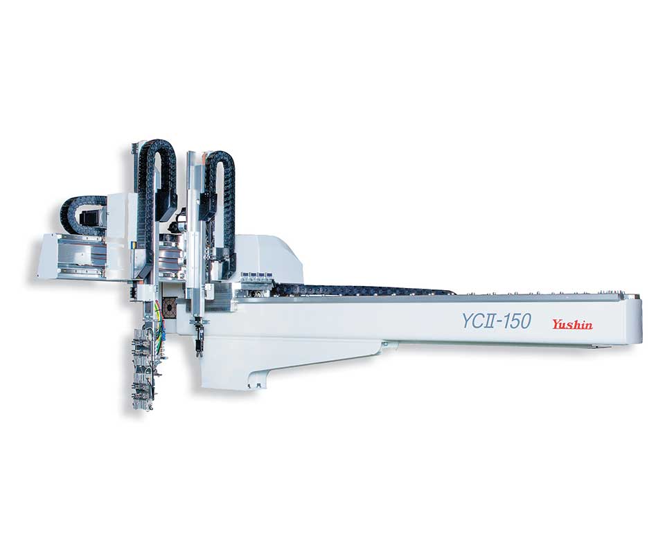
The first step in multi-arm evolution of Cartesian robots was the addition of a sub-arm behind the main lifting arm to remove runners from three-plate molds.
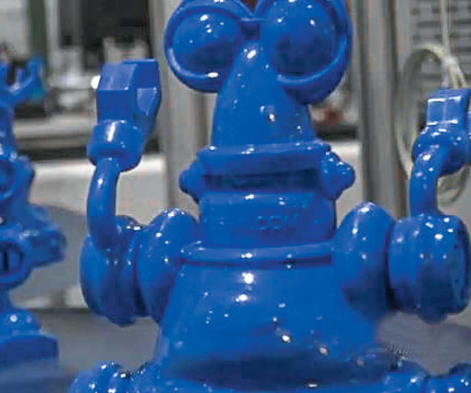
Assembly of Eddie, a toy robot, from eight parts in a family mold, was demonstrated with a dual-main-arm robot at NPE 2012 and 2015.
Double-main-arm robots have become common in applications requiring pre- and post-mold operations such as insert placement, in-mold label placement, degating, inspection, hinge flexing, and assembly.
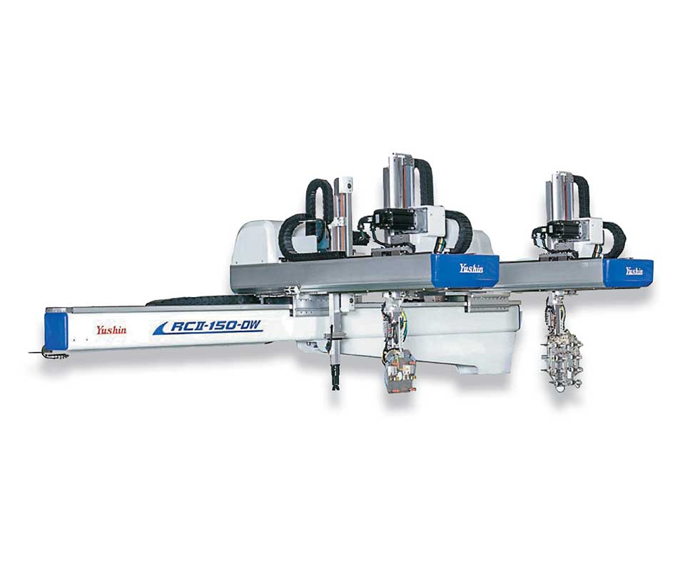
Robots featuring two strip or kick assemblies on one traversing stroke, like Yushin’s “Double Wing” design, have emerged in the last decade.
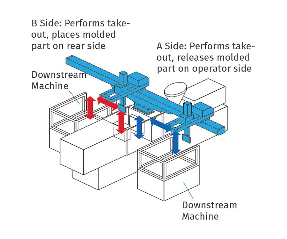
APPLICATION 2: Double Wing design with one main arm on each kick assembly permits parts to be released at both the operator side and rear side of the machine to maintain separation of RH and LH parts.
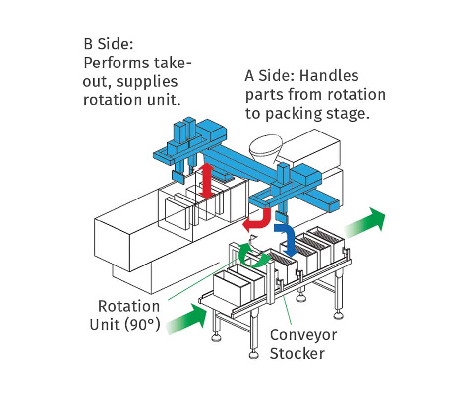
APPLICATION 3: Demolding and pack-out for short molding cycles. Main arm B with sub- arm removes parts and transfers them to a rotation unit for 90° repositioning. Main arm A takes the rotated parts and packs them.
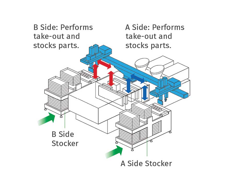
APPLICATION 4: Demolding and pack-out for ultra-short molding cycles. A- and B-side kick assemblies each have a main arm and sub-arm for demolding parts and packing them on operator and rear sides of the machine.
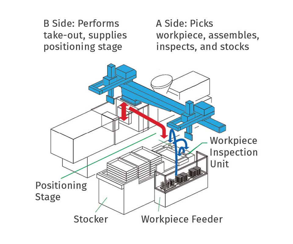
APPLICATION 5: Demolding, assembly and/or inspection and pack-out.
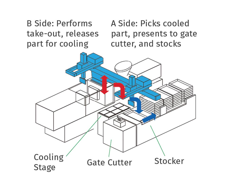
APPLICATION 6: Demolding, cooling, gate cutting, and pack-out.
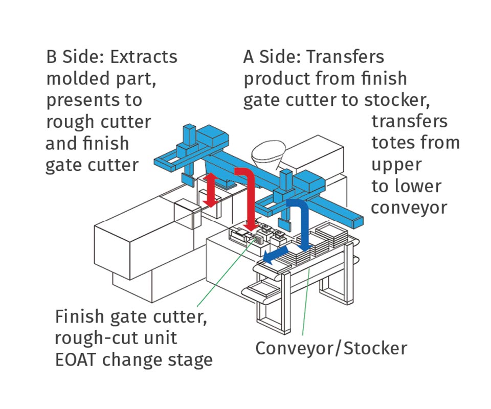
APPLICATION 7: Demolding, rough and finish gate cutting, and pack-out.


For many years, Cartesian-style robots have been the primary design for injection molding machines’ take-out robots. They normally were comprised of three linear axes: a strip stroke, a lifting stroke, and conveying stroke. The mold would open and the lifting stroke would position a gripping device to secure the molded parts in the mold. The strip stroke would move back, removing the molded parts and then the lifting stroke would retract, allowing the mold to close and continue the cycle. The conveying stroke then moved the parts, carried by the lifting and strip stroke axes, to an area where they could be discharged.
It was only a short time before the need to simultaneously remove runners from three-plate molds was solved with the addition of another lifting-stroke axis that was positioned behind the main lifting arm (see photo).
EVOLUTION OF THE SECOND MAIN ARM
Many years later, the secondary, light-duty lifting arm was replaced by a second primary lifting arm. Now the linear robot could be used for stack molds, simultaneously removing molded parts from both sides of a stack mold. These applications are very popular in packaging markets.
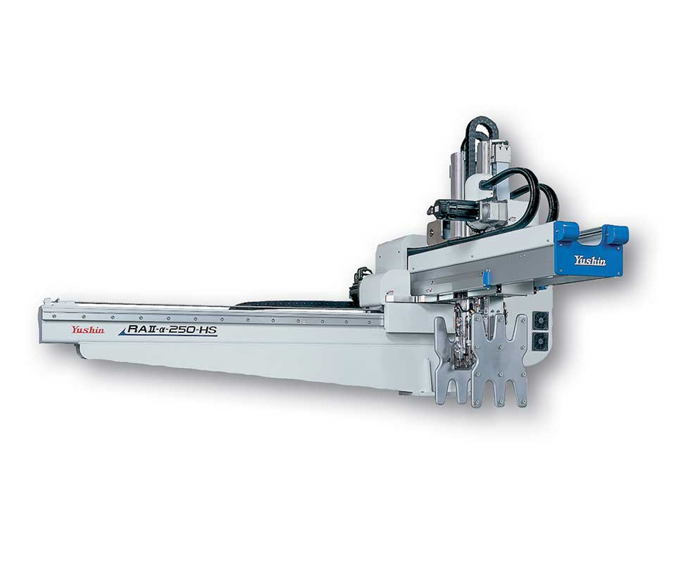
As the robot mechanics improved, programming became easier and the end-of-arm tooling (EOAT) grew more sophisticated, so new applications became possible. It has become common to use “Double Main Arm” robots for pre- and post-molding operations (photo opposite). Typical pre-mold operations include automatic placement of inserts in the mold before the plastic is shot. Those inserts could be machined or cast metal components, or even molded plastic parts for overmolding operations.
Double-main-arm robots have applications in a wide range of industries:
- Medical applications include overmolding threaded inserts or clear windows.
- Automotive applications include overmolding elastomeric skins or metal stiffening structures.
- Electronic and household-goods applications include overmolding RFI shielding or connector bodies encapsulating terminals.
- Military applications include embedded electronic circuitry or overmolding impact-deadening materials
Virtually all industries can benefit from in-mold- labeling (IML) applications. Those labels can be plastic film or rigid plastic or metal. Applications range from warning labels on lawnmowers to calibration markings on surgical instrumentation to identifying features in automobiles.
Another use for the second main arm can be to reverse the orientation of parts. As was demonstrated in Yushin’s booth at NPE 2015, medical marijuana vials were removed from the mold by securing the bottom of the containers with the EOAT.
However, they needed to be placed in the lid-closing station with the lid facing up. To ensure that the overall molding cycle would not be increased, a double-main-arm robot with opposing EOATs was utilized. After the parts were removed from the mold, the rear EOAT, which held the parts by the base, was positioned in front of the front EOAT. The parts were transferred to the front EOAT, which secured the open side of the containers. Now the containers were in the correct orientation or placement in the closing fixtures, and cycle time was not affected since that reorientation occurred during the move to the fixtures.
The second main arm also can be used for product assembly. As Yushin demonstrated at the 2012 and 2015 NPE shows in Orlando, an eight-part family tool was used mold and assemble “Eddie,” a toy robot (photo at top). The parts were demolded with the primary-main-arm EOAT. That EOAT was repositioned and six parts were transferred to the secondary main arm’s EOAT. As the first two parts were placed into an assembly fixture, parts on the second EOAT were repositioned to permit accurate placement on the first parts and clamping nests. When the complete assembly was finished, a third EOAT retrieved “Eddie” from his fixture and placed him on his feet on the conveyor leading to his anxiously waiting adoptive family. Eddie was produced in a little less than one minute without being touched by human hands.
Post-mold operations for a secondary main arm include deflashing, degating, inspection, and hinge flexing. By incorporating these and similar secondary operations on the robot’s second main arm, two significant benefits are realized. First, the operation can be performed as the parts are moving from the mold to the next operation. Since the robot does not have to place the parts into a fixed-location fixture or clamp and wait for the operation to complete, the total cycle can be shorter. If one or both arms are equipped with a single- or dual-motion servo rotary axis, the potential application range increases tremendously.
For example, some hinge-flexing applications cannot be properly accomplished with one end-of-arm tool. A secondary device to render the correct motion is sometimes required. In place of a piece of fixed equipment that requires the part to be held in position and eats up valuable cycle time, that device can be added to the second main arm. With that concept, the operation occurs as the robot is transferring the molded parts to their next operation.
This thought leads to the second benefit of a second main arm on the robot: Valuable floor space is made available for other uses. It may permit moving the presses closer to one another, or it may permit the addition of other labor- and inventory-saving items such as box-loading systems. Packaging the molded parts at the press with the use of the robot eliminates the manpower required to manually transfer parts from a conveyor to a tote for subsequent inspection and packaging. Wasteful queues of WIP are reduced and the increased potential of damage or loss is reduced. Taken individually, each of these benefits improves the company’s profitability and increases its perceived value to its customers. When multiple improvements are realized for an application, the ROI can be very attractive.
ENTER THE DOUBLE WING
Robot functionality advanced again in the past decade with the introduction of two entirely separate robot arms, each with its own strip, or kick, axis on a single conveying, or traverse, axis. Operated by a single controller, two arms could be mechanically coupled or they could operate independently. The latter is the case with the so-called “Double Wing” design (photo). This type of robot features two independent strip or kick assemblies on one traversing stroke. Each of the kick assemblies can be con- figured with one main lifting arm, or one main arm and one sub-arm, or with two main arms, or any combination of those configurations.
This single robot chassis permits operations that function independent of one another and act like two independent cells, yet are managed by a single controller. Advantages of this setup include reduced floorspace and capital cost savings of 10% to 15% over a conventional two-robot solution. Furthermore, value-added operations occurring at the molding cell reduce material-handling labor and storage space and reduce damage caused by additional handling. The end result is faster and lower cost throughput for your customer.
This design is well suited to multi-process automated molding systems, as indicated by these examples:
1. Two-color or multi-material molding.
- Mold opens, permitting the main arms to position the EOAT to secure and remove the molded parts.
- Main arm “B” traverses to the discharge area as main arm “A” transfers the molded part from the first mold to the second mold for overmolding a second color or material.
2. Maintaining total separation of RH and LH parts.
- Mold opens, permitting the main arms to position the EOAT to secure and remove the molded parts.
- Main arm “B” traverses to the rear-side discharge area as main arm “A” traverses to the operator-side discharge area. The molded parts can be released to a discharge conveyor or positioned in stocker systems.
3. Demolding and pack-out for short molding cycles.
- Mold opens, permitting the main arm(s) “B” to position the EOAT to secure and remove the molded parts.
- Main arm “B” lifts parts from the mold area, permitting the press to cycle. The “B” EOAT traverses to the handoff station and transfers the parts to it.
- The “B” arm returns to the wait position above the mold, while the handoff station rotates the parts up to 90°.
- The “A” arm retrieves those parts and, as it moves to the discharge position, rotates to provide the final orientation of the parts for release to a discharge conveyor or positioning in a stocker system.
4. Demolding and pack-out for ultra-short molding cycles.
- Mold opens, permitting the main arm(s) “A” to position the EOAT to secure and remove the molded parts.
- Main arm “A” lifts parts from the mold area, permitting the press to cycle, and transfers the molded parts to the operator side of the machine for discharge.
- As the “A” stage moves away from the mold, the “B” stage positions itself above the mold, awaiting the mold-open signal.
- Mold opens, permitting the main arm(s) “B” to position the EOAT to secure and remove the molded parts.
- Main arm “B” lifts parts from the mold area, permitting the press to cycle, and transfers the molded parts to the operator side of the machine for discharge.
- As the “B” stage moves away from the mold, the “A” stage positions itself above the mold, awaiting the mold-open signal.
5. Demolding, assembly, and/or inspection and pack-out.
- Mold opens, permitting the main arm(s) “B” to position the EOAT to secure and remove the molded parts.
- Main arm “B” lifts parts from the mold area and traverses to the discharge fixture(s). Once the “B” arm is clear, the “A” EOAT can perform secondary operations such as assembly and/or inspection. Once completed, the approved parts can be transferred to a discharge conveyor, or positioned in stocker systems. Rejects can be deposited separately.
6. Demolding, cooling, gate cutting, and pack-out.
- Mold opens, permitting the main arm(s) “B” to position the EOAT to secure and remove the molded parts.
- Main arm “B” lifts parts from the mold area and traverses to an open cooling fixture (or fixtures). Once the “B” arm is clear, the “A” EOAT can secure a cooled part and transfer it to a gate-cutting station. Degated parts can be transferred to a discharge conveyor or positioned in stocker systems.
7. Demolding, rough and finish gate cutting, and pack-out.
- Mold opens, permitting the main arm(s) “B” to position the EOAT to secure and remove the molded parts.
- Main arm “B” lifts parts from the mold area and traverses to a rough-cut gate-removal station. Once the “B” arm is clear, the “A” EOAT can pick the rough-cut part(s) and transfer to a finish gate-cutting station. Finished degated parts can be transferred to a discharge conveyor or positioned in stocker sys- tems. The “A” arm can also move full trays to a discharge conveyor.
8. Orientation and placement of multiple inserts for overmolding.
- The rear “A” EOAT secures the nested labels and traverses into position above the mold.
- Mold opens, permitting the front and rear “A” arms to position the respective EOATs in the mold.
- The rear “A” EOAT accurately transfers the labels to the mold.
- The front “A” EOAT secures the labeled parts and removes them from the mold.
- Both “A” arms rise from the mold area and traverse to a discharge conveyor to release the labeled parts.
- The cycle resumes.
This application was demonstrated in Sumitomo (SHI) Demag’s booth at NPE 2015 in a two-cavity cell that simultaneously molded two different-sized noodle cups with IML.
10. Orientation and placement of inserts for overmolding in a vertical injection machine.
- The “B” EOAT removes the over-molded part(s) from the lower mold half and traverses to the discharge conveyor or stocker.
- The “A” arm retrieves inserts from a feeder bowl or other staging device and places them into the lower mold cavity(ies).
Robots that offer many variations of configurations can lower risks by repurposing existing technology instead of creating new custom products for complex needs. Investigate robot vendors carefully for their range of products and experience, and select the best value and solution, not the lowest price.
ABOUT THE AUTHOR: Ronald Bryant is the manager of equipment sales at robot supplier Yushin America, Inc., Cranston R.I. Since the 1970s he has provided tooling and automation for sonic, ultrasonic, infrared, and thermal assembly of plastic parts and metals. He has also provided machine design and construction for film and paper converting, as well as robotic takeout and assembly systems for plastics. Contact: 401-463-1800; salesinfo@yushin.com; yushinamerica.com.


Related Content

Automation Evolution: From Robots to Work Cells, Solo Devices to Integrated Systems
Injection molding automation has progressed from devices to systems, from simplicity to more complex capabilities. The author traces this development through various levels of automation – all still available choices today – and analyzes the costs and capabilities for each level.
Read More
50 Years of Headlines … Almost
I was lucky to get an early look at many of the past half-century’s exciting developments in plastics. Here’s a selection.
Read More
Five Ways to Increase Productivity for Injection Molders
Faster setups, automation tools and proper training and support can go a long way.
Read More
System Offers 'Lights Out' Mold-Channel Cleaning & Diagnostics
New system automatically cleans mold-cooling lines—including conformal channels—removing rust and calcium, among other deposits, while simultaneously testing for leaks, measuring flow rate and applying rust inhibitor.
Read MoreRead Next

People 4.0 – How to Get Buy-In from Your Staff for Industry 4.0 Systems
Implementing a production monitoring system as the foundation of a ‘smart factory’ is about integrating people with new technology as much as it is about integrating machines and computers. Here are tips from a company that has gone through the process.
Read More
Advanced Recycling: Beyond Pyrolysis
Consumer-product brand owners increasingly see advanced chemical recycling as a necessary complement to mechanical recycling if they are to meet ambitious goals for a circular economy in the next decade. Dozens of technology providers are developing new technologies to overcome the limitations of existing pyrolysis methods and to commercialize various alternative approaches to chemical recycling of plastics.
Read More