
Improving Molding Process Capability: The Role of the Five Essential Pillars, Part 2
Each contributes to molded-part quality, and each must be optimized before production begins.

Five pillars contribute to the quality of an injection molded part, and each must be considered and optimized before production of the part.
Results of this experiment show that higher packing pressures will reduce the variation in part weights, which will be reflected in the part quality and dimensions.


The first installment of this two-part series (see May issue) discussed the concepts of process capability and the pressure-volume-temperature (PVT) diagram. Optimum packing of the part will lead to lower variation and therefore higher process capability (Cp) and process capability index (Cpk). The goal at every stage should therefore be to try and achieve the optimum part weight.
Achieving this optimum weight is related to the fill and pack-and-hold phases and therefore everything related must be considered. The temperature of the part must also be considered when ejected, since it is related to the dimensional stability.


There are five pillars that contribute to the quality of an injection molded part (Fig. 1). Each must be considered and optimized before production of the part. Cp and Cpk are measures of the capability of the molding process to produce good parts. The higher the numbers, the better the chances of molding acceptable parts—or the lower the chances of having rejects. Since process development and establishing a molding process constitute the last of the five pillars, it often becomes the burden of the process engineer to improve the Cpk. Achieving the required Cpk should be considered at every stage of each of the five pillars.
In the fill phase the cavity is filled with molten plastic. In the pack phase, additional plastic is packed in to compensate for shrinkage. The challenge is to add the plastic before the cooling melt reaches its no-flow temperature. If the part is underpacked and the plastic temperature inside the cavity is below the no-flow temperature, no amount of pressure will help in packing the additional plastic. Above the no-flow temperature, as the packing time and pressure increase, the part weight increases. The higher the pressures and times, the higher the part weight. (Parts can and will get overpacked, a topic that will be discussed in a later article.)
At the higher part weights, the number of molecules inside the cavity starts to stabilize and the variation between shot to shot therefore reduces. This reduction in the variation therefore helps to increase the process capability. The goal should therefore be to achieve maximum packing without overpacking the cavity.
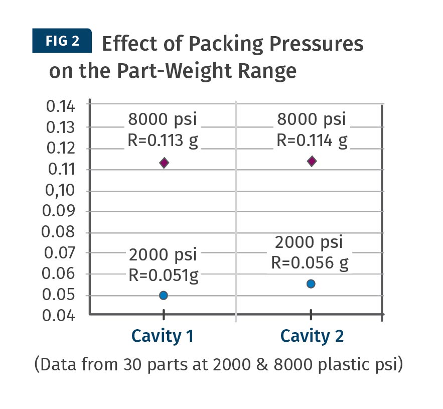
The proof is in the data (Fig 2). A two-cavity mold was used for this experiment. Thirty parts were molded with 2000 psi and 8000 psi of plastic packing pressure. The 30 parts were weighed, and the ranges was calculated. The results clearly show that higher packing pressures will reduce the variation in the part weights, which will be reflected in the part quality and dimensions.
THE FIVE PILLARS
Each of the five pillars plays an important role in achieving the goal of reducing variation. Note that the factors mentioned below are not the only factors. Once molders understand the goal of trying to achieve optimum packing, they must investigate means to achieve it.
Let’s look into some of these:
Part Design: One of the important rules in part design is to have flow lengths that will let the plastic be fluid enough not just to flow into the end of fill but also until all the packing of the part is achieved. This is defined for each material by the length-to-thickness (L/T) ratio of the part. Thin walls often increase the pressure required to fill the part, and the end of fill suffers. The available pack-and-hold pressure in the section with thin walls is not consistent, leading to the variation in the specific volume of fill, which in turn leads to shot-to-shot variation in the part dimensions and therefore lower process capability. One guideline to follow is not to have process-capability-required dimensions towards the end of fill if the flow lengths are long. Gating the part in a thin section and then trying to pack out a thick section can also pose issues of consistency in the thick section.
Material: As the melt is filled into the cavity, it cools and reduces in volume. This shrinkage must be consistent from shot to achieve process capability. Naturally, materials with high shrink value will have a higher variation compared with those having lower shrink values. For example, a PP will have more shot-to-shot variation than an ABS since the shrinkage of PP can be 1.5 to 2% or more, whereas it is 0.7% to 1.2% in the case of ABS. A filler can also influence this, usually reducing the shrinkage value. Materials can therefore influence the process capability.
For higher process capability, choose a material that has lower shrinkage. It is also important to consider the size of the part. The larger the dimension, the larger is the absolute value of the shrinkage. If a given material shrinks 1%, then the total reduction on a 1-in. part will be 0.010 in., but on a 10-in. part the total shrinkage will be 0.100 in. The variation in the 10-in. part will be higher than the variation in the 1-in. part and therefore may be less process capable. (For that same reason, it is very easy to control dimensions in micromolding, leading to high Cp values).
Mold Design and Moldmaking: Here, the gate location, amount of venting, and cooling are some of the factors that affect the process capability. Remember, in part design the L/T ratio is critical to the fill the part. The gate location should be such that the L/T of the part should not be close to the L/T limit of the material, or that will lead to inconsistency from shot to shot. In some cases, the choice of gate location is dictated by part cosmetics and/or by simple economics of the cost of the mold that can lead to lower process capability. The final customer should be made aware of this.
Vents in the mold help push the air out of the cavity and replace it with plastic. If the number of vents and/or the vent depths and/or the vent lands are not adequate, the air does not flow out of the mold at the required rate, restricting the plastic flow. Air pockets, voids, short shots, and burning can all result because of this restriction.
Once molders understand the goal of trying to achieve optimum packing, they must investigate means to achieve it.
This again leads to an inconsistent fill from shot to shot, resulting in lower process capability. The part must reach the material’s ejection temperature before it is ejected. Below the ejection temperature, the material has sufficient mechanical properties to be ejected from the mold and not be deformed. But the resin molecules may still have enough energy to move and settle at their location of choice, leading to post-mold shrinkage. To have uniform cooling of the part (think warpage again) and efficient cycle times, there must be effective mold-temperature control. Design of the cooling lines is therefore critical.
The cooling-line diameters—the distance from the part and between each other— should be such that when the part is ejected there are no “hot spots” that will again lead to inconsistent shrink and warp, affecting the process consistency. The cooling time will depend on the rate of heat removal from the cavity. To achieve a short cycle time, molders may decrease the cooling time. The part dimension may be achieved but the variation from shot to shot may be high, leading to lower process capability.
Injection Molding Machine: The melt must be homogeneous and not degraded. The barrel and the screw play an important role in achieving this goal. The molding-machine barrel must be chosen so that the plastic resides inside long enough for the plastic to melt, but not so long as to degrade. Therefore, the percentage use of the barrel should not be too low or too high.
This percentage is usually considered to be 15 to 20 on the low side and to 70 to 80 on the high side. The lower the number, the higher the chances of degradation, especially for heat-sensitive resins and/or longer-cycle parts.
The shear from the screw rotation must also be minimized. The higher the shear, the more you will experience issues with melt homogeneity. All these issues will result in melt consistency and therefore lead to lower process capability. The choice of the barrel size is therefore important. The process must also not be pressure limited.
Molding Process: As has been the underlying theme, optimal packing of the part will give the best process capability. The above four factors help in achieving this goal. The process engineer must realize not to compromise part dimensions for process capability. In other words, an underpacked part may achieve the required dimensions but may not have a good Cp value.
LINKING THE PILLARS
Apart from the above reasons linked to the five pillars, there are several other factors that are common among them:
Molding Process Window: This is related mainly to part design, mold design, and the mold build. The larger the molding window, the more robust and more capable the process. The leading reason for smaller process windows is parts beginning to flash at pack pressures slightly higher than those used to just pack them out. This indicates the mold shutoffs may be inadequate. It could also be because a section in the part is too thick, requiring the molder to use excessive pressures. If the machine tonnage is insufficient, parts will flash before they are packed out to an optimal level. Processors will therefore use lower packing pressure, leading to inconsistency.
Pressure-Limited Process: This is related to material selection, part design, mold design, or machine selection. A pressure-limited process will not allow sufficient pressure to fill and pack the part, leading to inconsistencies. A material with a low L/T limit can make a process pressure limited. Molders usually suggest using lower viscosity materials to help them fill the part easier at lower pressures. Thin sections in the part design can also increase the required pressure, making the process pressure limited. The location of the gate must be in an area that will let plastic flow easier into the ends of fill, making it less prone to pressure limitation. Sometimes in thin-wall parts, the required pressures can exceed 30,000 psi plastic pressure and therefore a machine with a higher pressure capacity must be selected.
The above are some of the factors to be considered. There are several other factors not mentioned here. It is important that each project is looked at with a holistic approach, avoiding the over-the-wall engineering approach. This will ensure the success of the project.
During this study there was another interesting observation that was made between cavity-to-cavity process capabilities. This will be discussed in a later article.
ABOUT THE AUTHOR: Suhas Kulkarni is the founder and president of Fimmtech, San Diego, an injection molding service-oriented firm focusing on Scientific Molding. Fimmtech has developed several custom tools that help molders develop robust processes, and its seminars have trained hundreds of individuals. Kulkarni is an author of the book, Robust Process Development and Scientific Molding, published by Hanser Publications. Contact:(760) 525–9053; suhas@fimmtech.com; fimmtech.com.


Related Content

Online Versions of Process Development Course and Software Launch
NPE2024: FimmTech is introducing online versions of its Nautilus process development software as well as its Scientific Molding and Design of Experiments (DOE) process development course.
Read More
Moving Beyond the Relative Viscosity Curve — New Method To Find Optimum Plastic Flow Rates: Part 2
Explore the use of the injection unit velocity capability, which determines a machine’s injection speed linearity to find optimum flow rates, and proposes a second method.
Read More
Use These 7 Parameters to Unravel the Melt Temperature Mystery
Despite its integral role in a stable process and consistent parts, true melt temperature in injection molding can be an enigma. Learning more about these seven parameters may help you solve the puzzle.
Read MoreRead Next

Improving Molding Process Capability: Understanding the PVT Graph, Part 1
Process capability is related to the variation in part dimensions from shot to shot. High values of process capability require the shrinkage of the material to be identical on each shot, which can be confirmed from the pressure-volume-temperature (PVT) graph.
Read More
Beyond Prototypes: 8 Ways the Plastics Industry Is Using 3D Printing
Plastics processors are finding applications for 3D printing around the plant and across the supply chain. Here are 8 examples to look for at NPE2024.
Read More
For PLASTICS' CEO Seaholm, NPE to Shine Light on Sustainability Successes
With advocacy, communication and sustainability as three main pillars, Seaholm leads a trade association to NPE that ‘is more active today than we have ever been.’
Read More