
Melt Fracture or Interfacial Instability? Different Ills Needs Different Cures
In blown film, clarity is often considered synonymous with quality.

Short waves occur when two layers merge inside the die and the thinner one accelerates too much (>300%). Long waves occur when a more viscous layer chokes off or encapsulates a less viscous one.
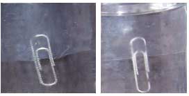
To tell if haze is caused by melt fracture or interfacial instability, immerse a film sample in water and weigh it down with a paper clip. Melt fracture, on the surface, disappears in water; interfacial instability, which is inside the film, doesn’t, so the paper clip appears blurry.
In blown film, clarity is often considered synonymous with quality. Haze is a defect. Haze can be caused either by melt fracture on the film’s surface or—in coextrusions—by instability inside the film where layers meet. The solutions to the two problems are very different, so confusing them only compounds the difficulty.
Melt fracture in its mildest form reduces surface gloss, though the roughness itself may not be visible to the naked eye. More severe cases show clearly visible transverse-direction zigzag lines. Interfacial instability occurs between layers of coex film and assumes short-wave or long-wave patterns. Short waves are like melt fracture but occur inside the film and may appear as uniform haze or as visible waves. Long waves appear as clearly defined TD striations (see illustration).


Interfacial instability is often confused with melt fracture in transparent film. But a simple test with a glass of water and a paper clip can easily distinguish the two. Put a film sample in the glass of water, using a paper clip to weigh the sample down. Melt fracture, which is on the surface, disappears in water (see photo). Water cannot affect the bumpy interface between layers, so interfacial instability doesn’t disappear in water, and the paper clip, seen through the film, appears blurry.
Cures for melt fracture
Melt fracture is caused by two distinct phenomena: pulsations in melt pressure and skin rupture. Pulsations in melt pressure are caused by a slip/stick phenomenon in the die. When polymer sticks and then breaks loose from metal surfaces in the die, melt pressure goes up and down. Pulsations are transmitted through the melt as it exits the die, much as earthquake tremors (also caused by a slip/stick release of pressure in the earth’s crust) ripple out from an epicenter.
Melt fracture caused by skin rupture occurs when the surface of the film is stretched too quickly on leaving the die. The newly emerged film swells and is pulled upward at the same time that it’s blasted with cold air. Skin rupture usually occurs only on the outside surface of the film when stretching and cooling occur too fast and cause micro tears. Skin rupture can also happen on the inside surface when very cold IBC air is used, but this is rare.
Melt-fracture problems can be fixed by changes in material, processing conditions, or equipment. The most popular solution is to add a processing aid to the resin to coat metal die surfaces and reduce the coefficient of friction. Fluoropolymers are common with LLDPE, but care must be taken not to add too much because they migrate to the film surface and cause problems with heat sealing and printing later on.
How much processing aid coats metal surfaces depends on shear stress. The coating is mostly stripped away from barrel surfaces by high shear stresses between the screw flight and barrel wall. However, in a spiral-mandrel die, shear stress is uneven. It’s lower inside the spirals and higher near lands and die lips. This leaves uneven amounts of coating and different coefficients of friction. It also changes flow patterns and makes the die less efficient at melt homogenizing. The result can be worse TD gauge variation.
Another raw-material solution is to blend in a higher-melt-index resin with lower viscosity to reduce overall shear stress in the die. Blending also helps reduce problems of skin rupture. Most operators, however, do not have the option to change formulations.
Another popular solution to melt fracture is to reduce output. This strategy is typically used by unskilled operators. However, it is better to adjust the extruder temperature profile to raise the melt temperature or use finer-mesh filters in the screen pack to increase recirculation flow in the metering zone of the screw. Increased recirculation gives more time for friction between the screw and barrel to increase the melt temperature.
Higher temperatures in the spirals of the die and at the lip will also reduce the shear stress that causes melt fracture, but care must be taken not to burn the polymer. Increasing melt temperature may also cause bubble instability (see PT, Dec. ’02, p. 36).
The most popular equipment solution to melt fracture is to use a wider die gap to reduce shear stress. Yet this approach may limit the ability to draw down thin films. LLDPE dies usually have gaps of 80-100 mils. It is difficult to produce LLDPE film thinner than 1-mil with a 100-mil die gap. A wider die gap may also change the balance of physical properties of the film and cause skin-rupture problems. Die gaps are usually optimized for a range of products and should only be changed by skilled personnel.
Stop interfacial instability
The raw-material solution to interfacial instability is to change the blend so that the viscosities of adjacent layers are more alike. Interfacial instability is also common when skin layers are too thin. Changing the layer-thickness ratio so that the interface is closer to the center of the flow channel also helps. Closer to the metal wall, drag resistance generates more shear stress. Changing formulations or layer ratios, however, isn’t usually left up to operators.
A common solution used by unskilled operators is to reduce output. This reduces overall shear stress between adjacent layers in the die and is effective for short-wave interfacial instability. Short-wave instability happens when two layers join inside the die. The thinner layer tends to accelerate; if it accelerates more than 300% it will exceed the critical shear stress of most polymers, causing the instability.
A better alternative is to adjust viscosities between adjacent layers to minimize shear stress. You can’t measure viscosity inside the die, but higher backpressure indicates higher viscosity. Higher melt temperature will reduce viscosity and backpressure. Temperature can be adjusted by raising the extruder temperature profile and adding finer-mesh filters in the screen pack to increase recirculation flow.
Long-wave interfacial instability is caused by large differences in viscosity between adjacent layers. The more viscous layer chokes off and encapsulates the less viscous layer. Since both extruder screws continue to turn, the pressure in the less viscous layer continues to climb until it overcomes the resistance and squirts into the melt stream. Again, higher backpressure in the die indicates higher viscosity.
Encapsulation is less likely to occur if pressures are similar when two layers merge into one flow channel. Adjusting extruder temperature profiles to match viscosity and adding or removing filters in the screen pack will bring backpressures closer together.
The only equipment solution to interfacial instability is to change the die itself. The size of internal flow passages and merge angles makes some dies more prone to interfacial instability than others. The preferred die has small merge angles and wider passages immediately after two layers join. Such dies, however, tend to be taller and to cost more. Modifying existing dies is slow, risky, and not recommended.


Related Content

How to Select the Right Cooling Stack for Sheet
First, remember there is no universal cooling-roll stack. And be sure to take into account the specific heat of the polymer you are processing.
Read More
Use Interactive Production Scheduling to Improve Your Plant's Efficiencies
When evaluating ERP solutions, consider the power of interactive production scheduling to effectively plan and allocate primary and secondary equipment, materials and resources on the overall production capacity of the business and conclude that this is a key area that cannot be overlooked.
Read More
How To Identify Resin Degradation in Single-Screw Extruders
Degradation can occur in many single-screw extrusion operations, and typically occurs due to minor design flaws in the screw. Here is how to track it down.
Read More
Reduce Downtime and Scrap in the Blown Film Industry
The blown film sector now benefits from a tailored solution developed by Chem-Trend to preserve integrity of the bubble.
Read MoreRead Next

Beyond Prototypes: 8 Ways the Plastics Industry Is Using 3D Printing
Plastics processors are finding applications for 3D printing around the plant and across the supply chain. Here are 8 examples to look for at NPE2024.
Read More
Lead the Conversation, Change the Conversation
Coverage of single-use plastics can be both misleading and demoralizing. Here are 10 tips for changing the perception of the plastics industry at your company and in your community.
Read More