Vacuum Blower or Pump Problems? Extend It, Fix It, or Make it More Efficient
Tips & Techniques: Conveying
The pump is a good place to start looking in you are having materials-conveying problems as it is the likely source of the trouble.
If plugged conveying lines are starving your machines, your vacuum-conveying pump or blower may not be providing enough vacuum or air-flow velocity.
A newer-style high-efficiency vacuum pump will provide a capacity of 3500 lb/hr while maintaining the 2-in. line diameter, saving the material and installation costs and of a new 2.5-in. system.
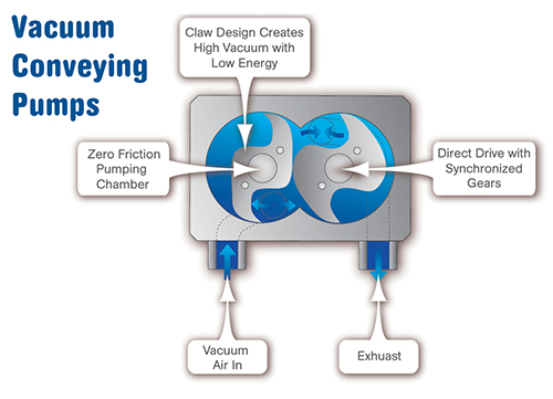
High-efficiency vacuum pumps convey more material over longer distances than either regenerative or positive-displacement blowers. The “hooked” or “claw” type rotors and the unique vacuum chamber create a system that consumes considerably less energy that either of the traditional types.


If you are plagued by plugged materials-conveying lines starving your machines, or problems with expanding an existing system, start by taking a look at your vacuum blower or pump, as it is most likely at the core of your troubles.
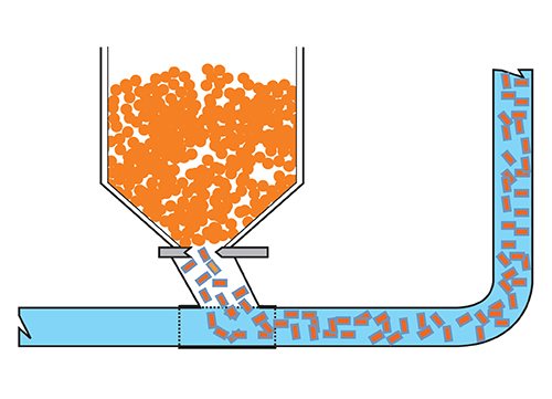
The vacuum blower has two basic functions, each of which is critical for maximizing efficiency of a vacuum-conveying system. The first is to create a sufficient velocity (air speed) at the pickup point to accelerate the material to get it moving in the airstream. For most pellets with a bulk density of 35 to 45 lb/ft³ and a pellet size of about 1/8 in., a pickup velocity of 3000 to 3500 ft/min is about right. Higher densities and irregular or larger particles may require a higher air velocity.


If the velocity is too low, the material will tend to slug as it exits the pickup box and the pipe will actually rattle as the material tries to get to a consistent, laminar flow. Additionally, when the receiver in a vacuum-sequencing system is emptying, the conveying cycle stops. During this time, the material, which is moving through both the horizontal and vertical sections, stops and settles in the horizontal section and at the base of the vertical section.
When the system restarts, the velocity must be sufficient to pick up and “re-accelerate” the material in the horizontal sections as well as the material plug that has settled at the base of the vertical leg. If your vertical lift is more than 25 ft, you may create a plug that will not easily clear. Installing a purge valve at the exit of the suction box or pickup wand will clean the line after each conveying cycle, eliminate the plugs, and generally increase your conveying efficiency. Be sure to figure the purge time into your conveying calculations.
The velocity profile in a system operating at 12 in. Hg vacuum with a 3500 ft/min pickup velocity will result in a terminal velocity in excess of 5000 ft/min. Controlling mid-range and terminal velocities can be a method to increase capacity and reduce angel-hair formation and wear and tear on equipment.
The second function of the pump is to overcome the pressure drop of the system. The pressure drop is the sum total of the vacuum required to move both the air and material as they are pulled through the system. Vacuum is created as air is drawn from the air-inlet point to the vacuum blower to pull the material through pipes to the vacuum receivers. If the vacuum required for the movement of the air and material exceeds the capacity of the vacuum pump, the vacuum relief on the pump will go off or the blower will overheat, creating plugs, starving machines, and causing other problems.
One often overlooked fact is that it takes energy just to pull the air from its entry into the pipe and through the system to the vacuum blower. For example, consider a 2-in. system with a material conveying distance of 350 ft, and a vacuum line back to the pump of another 350 ft. Such a setup requires almost 9-in. Hg just to move the air over this distance.
If the pump has a capacity of 12-in. Hg, that just leaves a scant 3 in. Hg for material conveying. A simple way to gain a little capacity when faced with long vacuum lines is to increase the diameter of the line. In the case above, going from 2 in. diam. to 3 in. would provide an additional 1.5 in. Hg for material movement.
PUMP OPTIONS
Historically, three types of pumps have been commonly used for vacuum conveying, and their application has been driven by the system requirements and vacuum capability of each type of pump. All of these pumps can create the correct air velocity (within reason) but the limiting factor is the vacuum capability.
Single-stage regenerative blowers operate at about 6 to 8 in. Hg, while two-stage regenerative blowers would typically be designed for systems operating at 10 in. Hg. Both of these pumps are direct driven. Unless a variable-speed drive is employed, air flow and velocity cannot be adjusted. Part of the popularity of regenerative blowers results from their compactness and relatively quiet operation.
The industry standby, the positive-displacement (PD) blower, is the third pump type. These pumps have been used for more than 40 years and can operate at 12 to 14 in. Hg. PD blowers are normally driven with sheaves and V-belts, allowing a certain adjustment capability. But be cautious when changing sheaves to get more velocity, as the higher velocity will increase the vacuum and may impact the horsepower requirements of the blower. Sound enclosures are often required to reduce decibel levels of PD blowers to meet OSHA standards.
Lately, a fourth kind of vacuum pump has been made available as a solution to high-capacity conveying problems. This “hooked-rotor,” high-efficiency pump has proven to be extremely efficient and can run continuously at 16 in. Hg, an increase of 30% to 40% over other pumps.
That 16 in. Hg is well below these pumps’ designed vacuum capacity of 22 in. Hg (or more in some cases). Applying one of these pumps to replace an existing PD blower in a system will increase the vacuum capability by 30% or more. These pumps are direct driven and run dry, so there is no belt maintenance or lubrication to worry about. An efficient vacuum relief, set at 16 in. Hg, is advisable, as operating at higher vacuum can damage vacuum receivers.
Both piping layouts and vacuum receivers can play a significant part in system efficiency. Be sure to minimize the number of elbows and avoid pipe inclines, as both affect pressure drop and hence available vacuum. If your material has considerable fines or angel-hair problems, pay special attention to cleaning the vacuum receivers. Plugged receiver screens and/or protective filters will increase the pressure drop, causing system shutdowns.
Occasionally a system just does not have either the right velocity or enough vacuum, and the end result is that you’ll experience either line plugs or starving of machines. After you have checked for leaks, plugged filters, and material-feeding problems, your only option may be to increase air-flow velocity and/or vacuum. If that’s the case, take a good look at your vacuum source.
Regenerative blowers are direct driven, and you are pretty much stuck with the air flow (velocity and vacuum) you have, unless you add a variable frequency-drive. Sheaves with V-belts are provided with the latter to create the correct speed and air flow on the PD blower. Sometimes changing the sheaves and increasing blower rpm will give you the right velocity, but that higher velocity will increase the vacuum and may push the pump or motor past its limits. It may also affect the horsepower requirements, so check with an expert before simply speeding up the blower.
In the past there were no options available to increase capacity of an existing system. Your only choice was to add an additional system or completely replace the existing one. The addition of the high-efficiency vacuum pump has changed that.
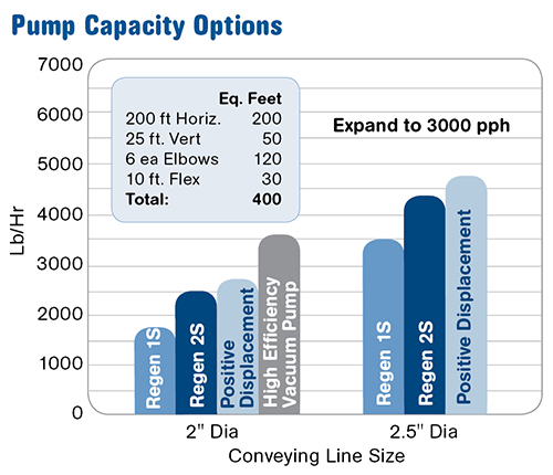
A quick look at the accompanying chart shows a scenario for various pump styles operating to a given set of specifications: 200 ft of horizontal distance, 25 ft vertical with six elbows and 10 ft of flex hose.
The accompanying bar charts show various capacities for a 2-in. diam. line over the specified distance.
Note that the PD blower tops out at about 2500 lb/hr, which is an increase over both single- and two-stage regenerative blowers. If the capacity requirements reach 3000 lb/hr and you have access only to regenerative and PD blowers, you will need to tear out the existing 2-in. pipes and install a new 2.5-in. system. Note that the high-efficiency vacuum pump will provide a capacity of 3500 lb/hr while maintaining the 2-in. line diameter, saving the material and installation costs and of a new 2.5-in. system.
So if you need to add machines to an existing system, clean plugged lines, or just increase efficiency, some simple, cost-saving options may be to add line purging, control mid- and terminal velocities, or take a step up in vacuum capability.
Related Content

Central Controller, Energy-Efficient Pump for Conveying
Wittmann debuts new control system and pump at Fakuma.
Read More
Redesigned Rotary Level Indicator
Red enclosure now rotates once installed to help ensure conduit entries are always pointed toward the ground, mitigating the risk of moisture damaging internal components.
Read More
Need a Better Way to Convey Powders from Point A to Point B?
Vacuum conveying systems for powders and difficult-to-convey materials involves a starting point and a destination where hazards need to be avoided along the way. Here are the top 10 tips to design a system to maximize movement and minimize dust exposure.
Read More
Finding Efficiencies in How Components Work Together
Auxiliary systems are vital to the proper functioning of a plastic processing line, and they can be a source of major cost and efficiency improvements.
Read MoreRead Next

Processor Turns to AI to Help Keep Machines Humming
At captive processor McConkey, a new generation of artificial intelligence models, highlighted by ChatGPT, is helping it wade through the shortage of skilled labor and keep its production lines churning out good parts.
Read More
Understanding Melting in Single-Screw Extruders
You can better visualize the melting process by “flipping” the observation point so that the barrel appears to be turning clockwise around a stationary screw.
Read More
Troubleshooting Screw and Barrel Wear in Extrusion
Extruder screws and barrels will wear over time. If you are seeing a reduction in specific rate and higher discharge temperatures, wear is the likely culprit.
Read More