
CAM Software Routes Thermoformer to Profitability
Geometry creation tools in Mastercam CAD/CAM software enable machining at angles needed to fit within the envelope of the equipment.
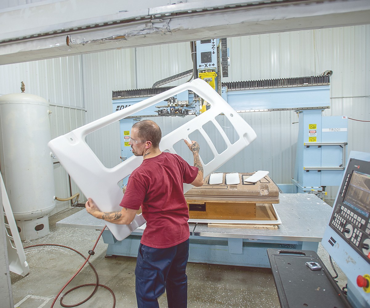
SAY Plastics’ James Young lifts a completed air-conditioning unit cover before sending it to a router for cutting and trimming. Mastercam Router software helps machine such large parts despite machine-size limitations.
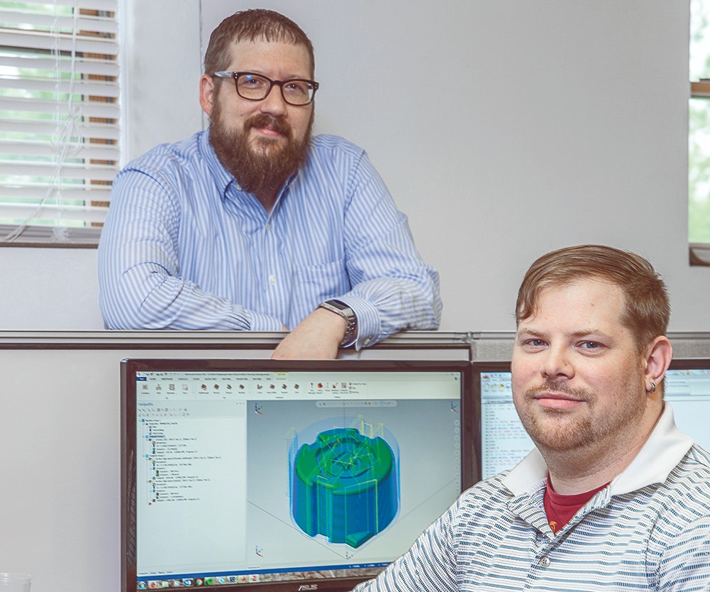
SAY Plastics’ programmer Jonathan Fake and Thomas Slaybaugh, engineering manager (standing), rely on powerful geometry creation tools in Mastercam CAD/CAM software to machine at nthe angles needed to fit within the envelope of its equipment.

Established in 1986, SAY Plastics, McSherrystown, Pa., designs and manufactures thermoformed components and packaging solutions for the rail, bus, material-handling, recreation, and entertainment industries. Services include re-engineering, protective-packaging manufacturing, design, vacuum forming, pressure forming, drape forming, CNC machining, fabrication, and assembly. The company forms a range of sheet materials, including acrylic, ABS, PVC, PC, and alloys.
Once parts are formed, operators perform surface-finish and trimming operations with CNC routers, specifically five-axis and three-axis machines. All models feature 5 Å~ 10 ft work surfaces to accommodate large parts. Despite these seemingly spacious work surfaces, SAY Plastics’ programmers face machine-size limitations. Mastercam CAD/CAM software (supplied by CNC Software Inc., Tolland, Conn.) helped resolve that issue and provided a host of process improvements.


“Mastercam has powerful geometry-creation tools that I can use to machine at the angles I need to fit within the envelope of our equipment,” says Thomas Slaybaugh, SAY Plastics’ engineering manager. Six years ago, he began using the software almost exclusively for multi-axis curve and drill operations. Surface machining soon followed, and the company has relied on the software ever since.
SAY Plastics needed a way to push the envelope—or at least expand it. Its three-axis CNC router, used mainly for machining molds and surface finishing, has height limitations. For example, if a machinist tries to cut a 108-in. part on a machine with a 120-in. “X” travel and a 20-in. spindle, cutting both ends is problematic.
The machinist must drag or push cuts on the two opposing sides. The CAM software enables him to do just that. “Mastercam allows us to slice a model that’s too high into multiple layers,” said Slaybaugh.
Using high-speed Dynamic Motion toolpaths, programmers can push CNC machines right up to their hardware limitations. Dynamic Motion technology uses proprietary algorithms to detect changes in the material as the tool moves through. It engages the entire flute length of cutting tools, so air cutting is minimized or eliminated, saving wear and tear on the tools and ensuring constant chip loading. The software calculates angles, feeds and speeds, while Dynamic toolpaths capitalize on the machine’s full capabilities.
Another CAM software feature that SAY Plastics programmers appreciate is the Verify function. It lets programmers check for gouges, view the finished shape of parts, and see how to include fixtures in the Verify simulation screen.
Productivity increases, and problems are visible before they ever make it to the shop floor. Programmers can verify on a separate thread while continuing to program, a productivity boost for those working with time-consuming processes such as 3D and high-speed toolpaths.
Most of SAY Plastics’ part designs are created with Solidworks modeling software. Designers open a file and explore features like analyzing distance and angle and position editing to resolve potential issues. One customer partnered with SAY Plastics to design and manufacture a large plastic cover to encase a toilet.
The end product was a bathroom safety feature for people with disabilities. Fitted alongside a toilet that is fixtured to a wall, the cover fills the gap between the wall and toilet, reducing the risk of a person falling off or sliding to the floor.
To machine the 4-by-3-by-3-ft parts, tooling was designed at an odd angle to prevent undercuts, which can hinder part ejection from tooling. The CAM software, specifically the translate and rotate options, allowed Slaybaugh to duplicate that angle within the software program. When the part was created, it was trimmed to a perfect part sitting on top of a perfect fixture, he said. Part testing revealed that modifications were needed, however. Using the multi-axis toolpath on a five-axis CNC router, Slaybaugh was able to modify the CAM program and direct the tool to trim deeper in some places and less deep in others. The first step in thermoforming a part is making a mold. Angles are drafted in Solidworks and, in some cases, Mastercam.
SAYtooling System is the thermoformer’s tooling development program geared toward new-product development, startup projects, and low- and medium-volume programs. It is far more appealing to enter a new product program spending $5000 rather than $30,000, notes Slaybaugh. But without reliable CAM software, the thermoformer would not be able to make tools in-house.
Considering that an aluminum mold that is contracted out can be made in-house for less than half of the cost, the savings are substantial. SAY Plastics passes those savings on to customers.


Related Content

Sustainable Materials is Focus of Thermoforming Exhibits at K 2022
Thermoforming equipment makers including WM, Kiefel, and OMV will showcase processing of recyclable and biobased materials.
Read More
An Automation 'First' for Non-Servo-Eject Trim Presses
Compact, flexible and configurable robotic system is said to be the first to enable thermoformers to fully automate product handling after a non-servo trim press.
Read More
Automation in Thermoforming on the Rise
Equipment suppliers’ latest innovations exemplify this trend driven by factors such as labor shortages, higher-speed thermoformers and tighter quality control.
Read More
Thermoforming PCR: An Equipment Supplier’s Pointers
Thermoforming PCR is not radically different from forming virgin, but variation in recycled materials can require extra care to get a consistent end result. Start by examining every aspect of the process from the sheet (and extrusion process if run inline) to the final trim.
Read MoreRead Next

Why (and What) You Need to Dry
Other than polyolefins, almost every other polymer exhibits some level of polarity and therefore can absorb a certain amount of moisture from the atmosphere. Here’s a look at some of these materials, and what needs to be done to dry them.
Read More
Understanding Melting in Single-Screw Extruders
You can better visualize the melting process by “flipping” the observation point so that the barrel appears to be turning clockwise around a stationary screw.
Read More