Avoiding Common Cosmetic Defects in Molded Parts
Identify familiar flaws and then work to eliminate them with these mold and part design tips, and process considerations.


Today’s consumers expect a certain level of finish in the products they purchase. Increasingly, style has become an important and deciding factor when comparing products. So, it’s important to understand how a part is manufactured to ensure that even basic design issues don’t become bigger problems for consumers or affect part functionality.
Injection molding comes with a specialized set of design guidelines, and design engineers who understand the best practices will increase their chances of catching these issues early and developing structurally sound and cosmetically appealing parts and products.


There are a number of common issues that we see in injection-molded parts at Protolabs. Here are some ideas on how to avoid them in the first place.
What a Drag!
Draft can be as simple as adding a degree or two to a wall to avoid right angles.
Photo Credit: Protolabs
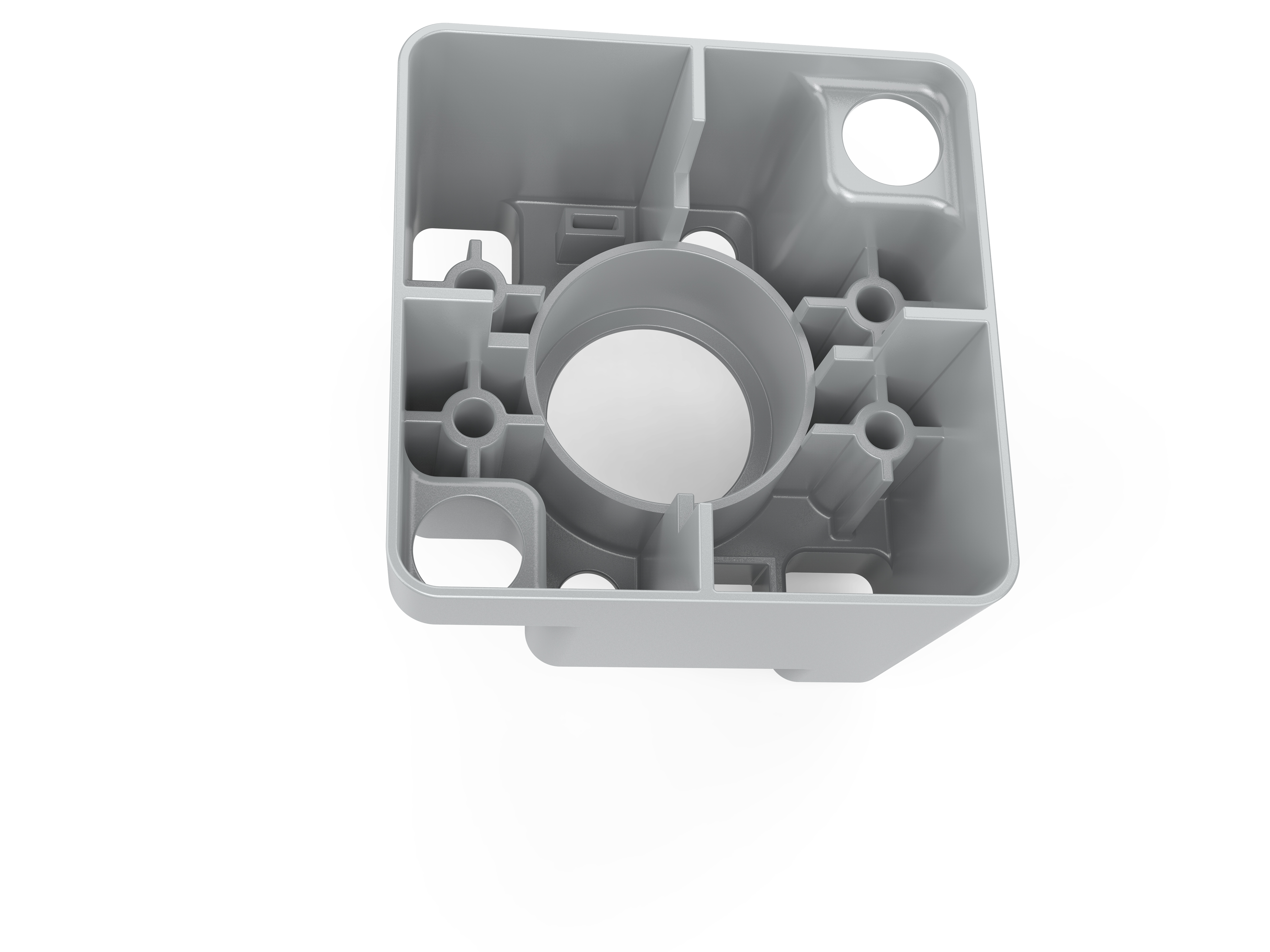
Injection-molded part aesthetics start with draft. Sufficient draft is an important part of any mold design, even with quick-turn tooling. Vertical walls, meaning those part surfaces parallel to the direction of mold operation, should have a minimum draft angle of a 1/2 degree, though 2 degrees is even better. Heavily textured surfaces may require 5 degrees or more. Without proper draft, part ejection becomes difficult if not impossible, and unattractive drag or scrape lines may occur.
Avoid Sink in Molded Parts
As its name implies, sink appears as a dimple or shallow depression on the surface of a molded part. It’s caused by thicker than normal cross sections, non-uniform part design or improper gate placement — the doorway through which hot plastic first enters the mold cavity. Polypropylene and acetal are very susceptible to sink, while fiber- and glass-filled materials are less prone to sink. We recommend assigning a recommended wall thickness to each material and advise that the minimum wall thickness be no less than 40 to 60% of a workpiece’s thickest section. Material flow within the mold should travel from thick to thin whenever possible, which might mean reorienting the mold cavity or placing the gate in an area originally reserved for a cosmetic surface.
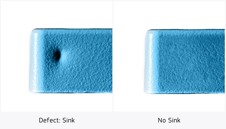
Meeting the recommended wall thickness for a material will help avoid sink. Photo Credit: Protolabs
A Brief Warp Tour
If you design a part with walls that are too thin for the target material, it’s likely to curl up like a potato chip. Warp, as this phenomenon is known, is easily avoided by following the same rules used with sink, namely staying within the general wall-thickness guidelines. Ironically, the glass-filled materials that work well with sink-prone parts are more susceptible to warp. That’s because, as the part cools, the glass fibers tend to line up in the same direction, creating internal stresses. You can improve your parts with internal support structures (such as gussets) to support thin walls or ribbing of large, flat surfaces.
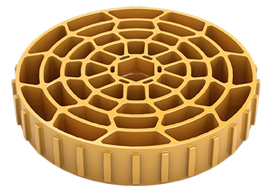
The type of uniform wall thickness displayed here is vital in preventing part distortion or warp. Photo Credit: Protolabs
Fleshing Out Flash
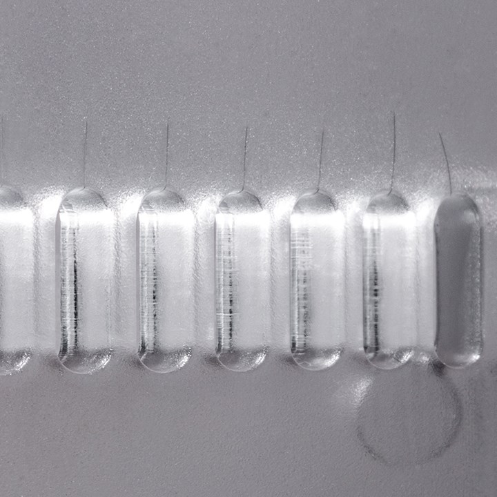
Trimming of parts is often necessary to avoid flash, depending on the material.
Photo Credit: Protolabs
Look closely at a rubber O-ring and you’ll see a thin line of material at its outermost periphery. That’s a parting line, the seam where the two halves of the mold come together. If you’re working with free-flowing materials such as Santoprene or unfilled nylon, a small amount of flash can sometimes ooze into the seam and typically requires trimming once the part has cooled for improved aesthetics. On a donut shape such as this, there’s little choice about the parting line location, but many orthogonal parts have sharp corners, which make a clean, crisp junction that’s a perfect place for the mold to separate. Flash or no, you should expect a parting line on most molded products. Digital manufacturers like Protolabs are able to identify the parting line location during the quoting process and may suggest ways of modifying the part geometry to avoid one.
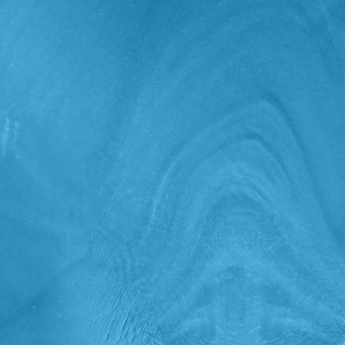
Adding and mixing colorants consistently can prevent swirling.
Photo Credit: Protolabs
Avoid Swirling in Injection Molding
From honey beige to cornflower blue, manufacturers stock a variety of colorants. These are mixed with natural resin pellets just before the molding run and are usually quite close to the target color. Still, the final product color may vary due to the polymer being used; texture and polish of the tool; and swirling during the mixing process. If you want an identical color match on your parts, it would be best to purchase color-matched pre-compounded resin from an external vendor.
Knit Lines and How to Solve Them
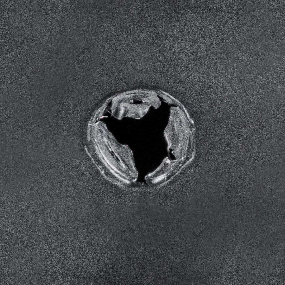
Worried about those fine lines that look like hairline cracks in your injection-molded part? Don’t be. Those are knit lines, formed when two opposing flows of material join together in the mold cavity. Commonly seen at the edge of a hole or other cored feature, as a rule, knit lines are purely cosmetic but may create a physical failure point if present in an area of the part that receives substantial stress, such as the head of a screw. In this case, designing a strengthening boss feature around the hole is a good precaution, or just skip the hole entirely and drill it afterward.
Knit lines have the potential to create structural issues for parts in the areas where they’re located. Photo Credit: Protolabs
Surface Imperfections and Finishing Options
If you select a PM-F0 noncosmetic finish on a tool, the finished part will likely show small, circular, end-mill marks and tool transition lines. If you need a surface finish that’s more cosmetically appealing, it’s generally a simple, if more expensive, matter to manually polish the tool. A PM-F1 finish removes most tool marks, while an SPI-A2 will be smoother than a fresh jar of peanut butter.
Texturing via bead blasting is another option that generally leaves a uniform matte finish (except in thicker areas) around knit lines and in darker materials. Bear in mind that deep slots and cavities are difficult to reach for polishing and texturing, and that fine finishes may affect turnaround time because of the additional effort needed for polishing. Suppliers sometimes offer multiple surface finish options to choose from (like pad printing and laser engraving) as well as finishing options (like mold texturing and part marking).
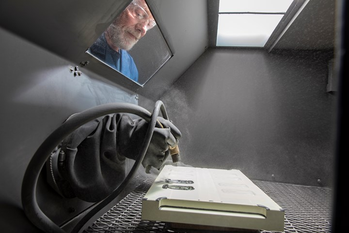
A secondary operation like bead blasting can ensure a uniform finish. Photo Credit: Protolabs
Vestiges in Molding
Gate vestige is that small ugly spot at one end of the part left by removal of the gate after molding, usually with a side cutter or razor knife. It’s an unavoidable fact of injection molding. For the most part, the only thing that can be done to avoid it is to orient the part in the mold such that cosmetic surfaces are unaffected. For example, when molding a Statue of Liberty replica, the gate should be placed on the soles of Lady Liberty’s feet. When submitting a design to an outsourced manufacturer like Protolabs, always be sure to speak to an applications engineer to ensure surfaces that require a vestige-free appearance can be accommodated. There may be options to change a gate style depending on the material and part geometry. It is much easier to do this during the review stages rather than after the mold design stages have begun.
Jets, Orange Peels and Other Molding Issues
There are several other problems that can crop up with injection molding, some of which can be tied back to wall thicknesses that exceed general recommendations:
- Drag Marks, usually caused by insufficient draft, are when the part drags along the mold wall during mold ejection, marring the surface of the part.
- Jetting, a wormlike swirl that appears near very thick gate areas, is caused by temperature variations within the material flow.
- A surface that looks like an orange peel can be caused by flow variations in the mold cavity, usually in thicker sections of the part.
- Silvery streaks and material flaking are known as splay and can occur as a result of moist or degraded resin. It can also be caused by material shear due to higher than normal screw speeds.
- Blush, a cloudy discoloration normally found near gate areas, is often caused by improper fill speeds, but proper part geometry and gate placement also play a factor.
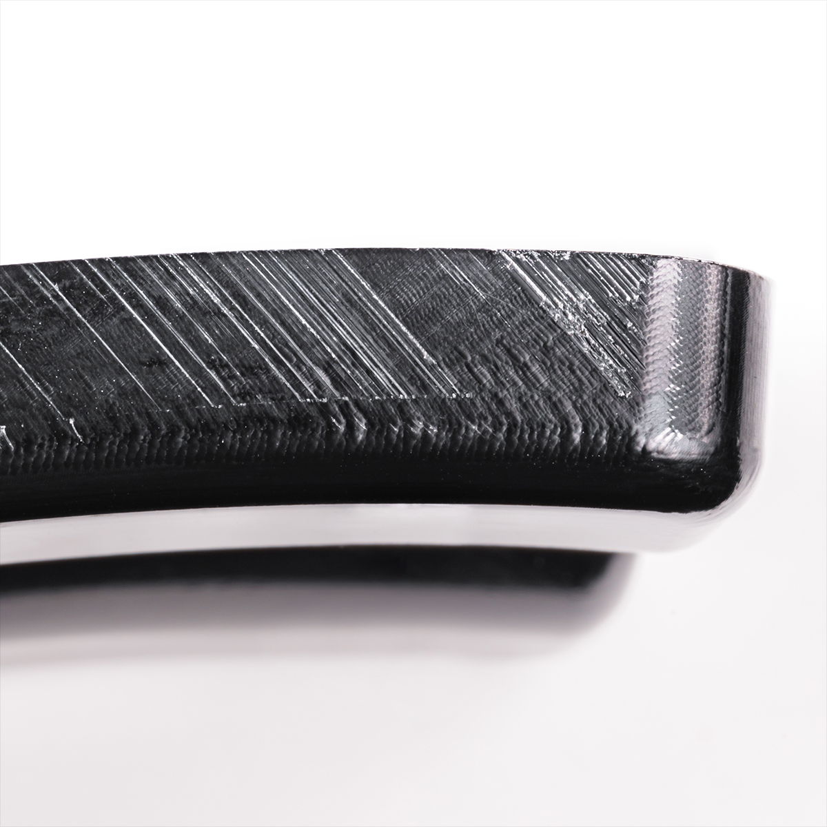
A draft adjustment or a new finish option will help prevent drag marks.
Photo Credit: Protolabs
Thankfully, most of these issues can be resolved through slight modifications to part design and/or selecting a different material. Difficult part geometries often require fine-tuning of the molding temperature, injection speed, hold times or all three. Material selection also plays a big part with cosmetics. Two examples of this are polypropylene and HDPE, which tend to sink more than polybutylene or acetal, but flow better into small part details. It is possible to test different materials using the same mold, but unfortunately shrink factors may prevent parts from having dimensions that match the CAD. In some cases, after testing multiple materials, a new mold may be required for further testing or production parts.
About the Author: Rob Young is the senior global product leader for injection molding at Protolabs. Young has nearly a decade of experience in digital manufacturing and specializes in on-demand production and supply chain optimization for Industry 4.0. He came to Protolabs after working with early stage startups at the Ina Mae Rude Entrepreneur Center and Center for Innovation Tech Incubator in Grand Forks, North Dakota. Young holds a B.B.A. in Entrepreneurship from the University of North Dakota. Contact: 877-479-3680; rob.young@protolabs.com; protolabs.com.
Related Content

How to Select the Right Tool Steel for Mold Cavities
With cavity steel or alloy selection there are many variables that can dictate the best option.
Read More
Formulating LLDPE/LDPE Blends For Abuse–Resistant Blown Film
A new study shows how the type and amount of LDPE in blends with LLDPE affect the processing and strength/toughness properties of blown film. Data are shown for both LDPE-rich and LLDPE-rich blends.
Read More
Tunnel Gates for Mold Designers, Part 1
Of all the gate types, tunnel gates are the most misunderstood. Here’s what you need to know to choose the best design for your application.
Read More
Understanding Strain-Rate Sensitivity In Polymers
Material behavior is fundamentally determined by the equivalence of time and temperature. But that principle tends to be lost on processors and designers. Here’s some guidance.
Read MoreRead Next

How to Reduce Sinks in Injection Molding
Modifications to the common core pin can be a simple solution, but don’t expect all resins to behave the same. Gas assist is also worth a try.
Read More
Injection Molding: Processors: Teach Part Designers The Golden Rule
Make sure the designers you work with understand that there are limits to what processing can do.
Read More
Identifying and Correcting Splay
Splay adjustments can be a simple fix, or can require several hours of babysitting a press and head scratching. Learn to find the root cause.
Read More