
CAD Evolution For 3D Mold Design
Specially tailored packages of 3D computer-aided design software have been available to injection mold designers for at least a decade.

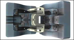
CAD tools for mold design are improving their capability to define and analyze some of the most criticial aspects of the mold model—core and cavity geometry, parting-line creation, and parting surfaces (Photo: Delcam).
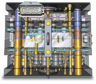
On-line libraries of standard components simplify tool-design tasks by making it easy to import ready-made geometries for pins, screws, and other commonly used components. (Photo: VX Corp.)
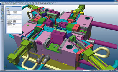
Analysis programs within mold-design software can evaluate the placement of side actions, lifters, or core pulls. (Photo: Vero Software)
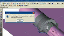
“Wizards” and other “smart” tools that detect and fix design flaws such as invalid parting surfaces are among the enhacements in the latest versions of mold-design software (Photo: Clear Cut Solutions)
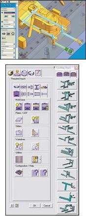
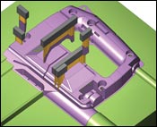
Mold wizards can help designers create cooling lines. Users can create their own templates that can be applied to multiple models. (Left: Delcam. Above: VX)
Several mold design modules now include programs to generate EDM electrode designs automatically. (Photo: VX Corp.)
Specially tailored packages of 3D computer-aided design software have been available to injection mold designers for at least a decade. Such software reduces the time required to generate the internal and external “infrastructure” of a tool by automating frequent or repetitive tasks, importing pre-configured standard components, and avoiding errors by “remembering” user-specified “rules” of mold design. “The automation of routine operations means that standard calculations on mold dimensions can be executed more quickly and with less chance of errors, speeding design times,” says Peter Dickin, marketing manager for Delcam, a U.K. based software supplier.
Adds Bill Genc, president of Clear Cut Solutions, “The aim of mold-design software is to allow the user to concentrate on the more complex aspects of mold planning while automating or simplifying more routine tasks, which can cut down design time, improve the overall quality and efficiency of the tool, and ultimately reduce production costs.” His firm is a U.S. reseller of TopSolid CAD software from Missler Software in France.


Today’s typical mold-design CAD package features programs or modules to build and view a full representation of the mold, which includes generating core and cavity from the part model, parting-line splits, optimization of parting surfaces, mold-base selection, and addition of shutoffs, cooling lines, runner systems, gates, slides, lifters, ejectors, columns, spacers, guides, nozzles, screws, and pins.
Mold-design software may also contain or link up with on-line libraries of standard mold components from companies such as D-M-E, Hasco, Futaba, and Progressive Components. These parts can then be imported directly into a 3D solid or surface program.
Mold CAD software suppliers have not only improved many of these mold-planning functions, but are bringing in a host of additional or enhanced capabilities, such as more graphic visualization tools, preliminary mold designs for “quick quoting,” rapid modeling of EDM electrodes for special part features, and the ability to create and manipulate holes, pockets, cavities, or side actions.
Other examples of features being added to tooling CAD packages are mold “feasibility” tools that evaluate the overall quality and moldability of a tool; flow and cooling simulation technology as a means to check material flow problems, cycle times, or potential stresses and warpage; and new ways to handle tooling data, such as user-created templates that set rules or constraints—e.g., draft angles, minimum steel thicknesses—that can be moved from one model to another.
Mold designers may work with part models created in other CAD software, which can lead to problems in importing data or generating correct dimensions or tolerances. Errors can result in gaps between surfaces of the part or tool, which can be solved by data translators, healing programs or more “tolerant” mold-design modules.
Software suppliers agree that one of the most critical areas of the mold model is the creation of the core and cavity and the parting-line split. This is due to the complexity of the geometry coupled with the need to create the most simple and effective design for part removal and overall tooling cost. With early software, mold designers would divide the surfaces of the part model manually and place them on separate levels to create the core and cavity. The parting surfaces were created piece by piece from the edges of the model, and then a complete split surface was generated by filling in any gaps and trimming back any overlaps, says Delcam’s Dickin. Needless to say, it was a very time-consuming task. Users also had to design pins, slides and other components on the surface of the core or cavity as well. Today’s software does more to help the modeler create better quality parting lines faster and with built-in “intelligence” that can suggest the geometry and position of the split.
Suppliers say such productivity advancements are critical to moldmakers today. “Injection molding part designs are becoming more complex due to parts consolidation, while at the same time the molder or customer requires the tooling sooner, so the mold has to be created and fabricated more quickly. Part designs are combining more features, more curvy shapes, more textures, or more challenging undercuts,” notes Dickin.
INDEPENDENT VS. INTEGRATED
Moldmaking CAD software comes from a variety of sources. There are independent packages from companies like Cornerstone Technologies or R&B Mold and Die Design Solutions. In truth, they do not run on their own, but as an add-on to other vendors’ CAD packages.
Alternatively, a mold-design module may be part of a CAD package designed primarily for part design, such as from Kubotek. Mold-design modules are also part of software packages whose main focus is on CAM for machining, such as from Cimatron, Delcam, and Sescoi. Suppliers of integrated CAD/CAM packages like TopSolid, Vero Software, and VX Corp. also have mold-design modules. And such modules also appear as part of a comprehensive, “end-to-end” or “enterprise” suite of tools for part planning through tool fabrication, offered by firms such as Dassault Systems, Parametric Technology Corp., or Siemens PLM (formerly UGS).
Tying the mold-design software to upstream part modeling or downstream CAM can help reduce errors in understanding the design or manufacturing intent, avoids data-translation issues, and can allow for more rapid adjustments to revisions, says Jeff Jajae, marketing and business manager for Sescoi USA, a supplier of CAM software with mold-design functions.
“The key point for integrating the different aspects of design is that a moldmaker is usually not doing the part design,” adds Hari Sridharan, v.p. of engineering at Cimatron, which supplies CAM software specifically for plastics molds. “If both the part designer and mold designer are using the same software, it creates a more seamless data environment. When there is a change to the product, it also changes the mold plan. Not being integrated can mean lost time in data translation and reprogramming. So having an integrated solution and working within the same data structure is important.”
PARAMETRIC OR HISTORY-FREE?
Mold designers can create their tool models using 3D solid modeling or surface-modeling software, or they can use programs that provide both types of functionality within one program. Solid modeling typically involves part features that have a thickness, while surface tools make shell-type geometries. Exterior mold surfaces like the core, cavity, or parting line, and interior components such as a runner system can be designed with either system, though they may handle the tasks in different ways and be easier or more difficult to use.
Data developed in a solids or surface environment can be managed two ways. A parametric model keeps a history of the chronology of the mold design and also has intelligence allowing for relationships to be formed (“associativity”) between different patterns or features. For example, if a designer selects a mold base of a certain size, it is associated with a certain number of drilled holes, created with certain spacing on the plate, and having a certain diameter and depth. The advantage of a parametric modeler is its automatic updating of groups of related objects when an item associated to it changes. It also allows the designer to save and reuse all of the settings again in another tool plan, saving time.
A disadvantage of parametric software is that the designer cannot make even a small change to a feature without impacting all related groups of objects. So expanding one hole in the mold base may cause all the holes in the base to change—even if that is not what was intended.
So-called “history-free” modelers (also called explicit, dynamic, or direct modelers) do not associate one pattern or feature with another, do not create a history tree, and do not link associated components, allowing individual features to be changed independently. Users can thus create unusual geometries for components or patterns without affecting other standard components. Users can update the mold design quickly when just a few features are adjusted.
The downside is that changes to a duplicated element or feature such as a hole, column, or pin—which would be repeated for each element automatically by a parametric modeler—must be done one at a time in a history-free environment. And the designer must remember to change any components relating to that component—such as remembering to change the hole size if a pin is resized. Parametric modelers reduce some risk of errors—and save time in such circumstances—by updating associated features automatically.
One fairly new development is that some CAD packages allow users to assign parametric and non-parametric functionality to different features in the same model. This is growing more common as some vendors of parametric modelers are now adding history-free direct modeling commands to their software. “They are incorporating direct modeling to quickly select certain features instead of interacting with the entire model through the history tree,” says Robert Bean, executive v.p. of Kubotek, which offers its KeyCreator software for part and mold design.
Parametric Technology Corp. (PTC), supplier of Pro/Engineer parametric CAD software, last year acquired CoCreate of Germany, which offers the OneSpace direct surface modeler. PTC has no plans to merge or blend the two systems, but rather is looking to offer more choice to mold designers, says Sandy Joung, marketing director. “For companies with a platform-driven product strategy, where they make a product and derivatives and plan to reuse the model, they require a parametric solution to capture the intent and intelligence. If a company is doing a one-off design, which is typically the case in consumer electronics such as cell phones or printers, where the product life cycle is short and the reuse of data is low, then an explicit modeler could be a choice. They are two entirely different approaches,” notes Joung. Pro/Engineer works in a solids-only environment, while the OneSpace has surface and solids elements.
NEWS FROM INDEPENDENTS
Cornerstone Technology’s Expert Mold Designer (XMD) software, which is a separate add-on for KeyCreator part-design software from Kubotek, has a brand-new Mold Feasibility module that evaluates a part’s moldability by examining drafts, undercuts, wall thicknesses, etc. The software indicates the complexity of the tool that would be required and molding problems that could arise, and also indicates design changes that might be required to produce a moldable part, says Cornerstone president Paul Coleman.
His company is also working on a novel software development that will allow users to create transportable parametric rules for mold design. “The user can develop parametric rules for each aspect of the design. In addition, the constraints that the mold designer creates will not be tied to a particular mold plan. The designer will be able to place those rules and associated component geometries into a custom template, which can be applied to any other mold design,” says Coleman. “Most CAD packages will not allow you to pull out the rules or custom designs created for a particular mold job, so this method brings a more efficient reuse of knowledge,” he says. Users will be able to tweak the customized “rule engine” to get the software to react the way they want. Cornerstone has a patent on this Virtual Moldmaker software, which is still in R&D. One feature currently being tested is the software’s intelligence related to spring-loaded mold functions. The software will be able to recommend the appropriate type of spring type for a given mold based on designer preferences. The software may also be able to help determine tooling quotes based on the designer’s rules.
R&B Mold and Die Design Solutions has upgraded its Computer Aided Mold Design (CAMD) software, which runs as an add-on package for CAD software like SolidWorks or CoCreate. R&B enhanced its program for generating cooling lines to allow complete cooling designs to be generated automatically from 2D and 3D sketches, according to George Berold, v.p. of marketing. During the preview phase, designers can add or modify plugs, connectors, or baffles. The software also has a brand-new module for automatic generation of an EDM electrode, Berold adds.
R&B is also developing a new MoldXpress program that creates a preliminary mold design that lets users develop a quote for the tooling job. It expects to commercialize it sometime in the third quarter. The Israeli-based company is setting up a U.S. sales subsidiary in Mississippi.
INTEGRATED SYSTEMS ADVANCE
Missler Software is coming out this month with new analysis tools for its TopSolid Mold parametric module that will allow users to complete complex parting-line splitting with less frustration. The new Parting Line Verification tool helps designers find the position and geometry of the parting line. It separates the mold block into two associative shells (surfaces) and then provides information about the quality of the parting line such as interferences with features on the surface. The new Invalid Parting Line analysis tool can determine misaligned parting surfaces or otherwise inaccurate parting faces and can help the designer heal such flaws.
In addition, the new Predefined Mold Sub-Assemblies tool allows designers to create and organize assemblies in their tool by hardware, bolts and screws, ejector pins, standard components, and machined elements.
In coming months, Missler also will integrate flow-simulation software from Moldflow Corp. It will be accessible by clicking on an icon.
COMPLEMENTING CAD
There is also news from CAD vendors that have extended their part-design packages with mold-design functions. Kubotek has enhanced the cut-and-paste (“prune and graft”) feature in its KeyCreator 7.0 software that allows mold designers to add or remove features such as pockets or side actions more easily than before. The software also has improved its mold-parting command for generating parting-line surfaces. Kubotek added a new validation program that can compare different versions of a mold design and highlight even the most subtle changes. Transparent versions of each design are overlaid, and the program highlights changes in red. John McCullogh, product marketing manager, says the next version in development, KeyCreator 7.5, will have tools that make direct (history-free) modeling more efficient.
Mold wizards can help designers create cooling lines. Users can create their own templates that can be applied to multiple models. (Left: Delcam. Above: VX)
Meanwhile, new Version 15 of Vero Software’s Visi surface, solid, and wireframe software adds more than 60 new parametric library components to its Visi Mold hybrid software. These provide a greater selection of features, including moving components such as lifters. Visi Mold also adds eight new automated functions to achieve core and cavity separation and runoff geometry. Users can define the parting line in a free-form approach with a dynamic split plane, or create it plane by plane with a “split-plane builder.”
Vero is also more fully integrating its relatively new Visi Flow mold simulation software package into the suite. (The latter was developed from the TMConcept software suite acquired from Plastics & Computer Inc. in late 2006.) New tools for designing cooling lines can be run in the simulation.
VX Corp.’s mold-design tools include a new parametric mold library that includes all commonly used tool components and has a new intuitive graphic user interface. Other mold enhancements include auto-zoom and wireframe-supported parting-line tools that help find and fix parting-line gaps generated during the mold split. This is especially helpful for users who wish to save time by skipping the healing process and going directly to splitting their customers’ part into core and cavity mold surfaces.
VX also offers enhanced tools for generating parting lines on complex surfaces and healing programs that repair corrupted geometries, fix undercuts, and analyze and repair draft angles. In recently released Version 13 of its CAD/CAM suite, VX added real-time draft analysis that lets mold designers repair draft angles while in analysis mode, thus allowing them to work uninterrupted for higher productivity.
VX’s mold modeling has been combined with Mold Expert, a library of “smart” components for creating mold assemblies with parametric cooling channels, sliders, and ejectors. Users select the component and the software calculates the required lengths, clearances, and manufacturing methods.
THE CAM CONNECTION
Cimatron added several new tools that speed parting-line development in Version 8 of its CAM-focused Cimatron E-Mold software. The new release also features a new Quick Electrode module that helps to design the electrode up to 80% faster than with the previous program by grabbing data from the design software to program the EDM sinker producing the electrode. This approach eliminates human input, reducing the chance for errors. Cimatron also added a viewer that allows interaction between the part-design engineer, mold designer, and toolmaker. They can view 3D models together in an online conference.
VX Corp. has a new EDM electrode design “wizard” that makes 3D definition and 2D layout of electrodes fast and simple, says Bob Fischer, v.p. of sales and marketing.
CAM-focused software supplier Delcam says its Powershape CAD software, which incorporates the Toolmaker mold design module, has a special Power Feature option that allows users to set the level of associativity of parametrically designed solid components. The program applies history-free surface-modeling intelligence to core and cavity generation, while the remainder of the mold design is completed in 3D solid geometry. All parametrically designed components and related dimensions and tolerances can be modified using a single “global” edit for multiple groups of components, or they can be modified individually. Since most mold components are made up from fairly simple prismatic geometry, Dickin explains, solid modeling is the most appropriate method for the overall mold. But cores, cavities, and slides require surface-modeling tools, he notes.
Sescoi has added a simple mold-modeling package to its WorkNC CAM software to ease translation or healing issues for moldmakers, says Jeff Jajae, marketing and business manager. Its WorkNC-CAD software, included with its WorkNC CAM package, provides integrated mold-design modules that enable users to add, extend, or modify surfaces, automatically generate parting surfaces, and create internal mold components. There are also visualization tools to check draft angles and backdraft conditions. Moldmakers also have the ability to design electrodes themselves within the system. The intelligence on the CAD side comes together with the CAM functions for more automatic feature recognition and tool-path generation, says Jajae. ”


Related Content

MPM’s Second Act: Keeping Injection Molding, Moldmaking in the Midwest
Larry Austin’s 35 years at a highly successful injection molding company inform much of what he does and doesn’t want in his second act in plastics owning an injection molding company.
Read More
How to Design Three-Plate Molds – Part 3
There are many things to consider, and paying attention to the details can help avoid machine downtime and higher maintenance costs — and keep the customer happy.
Read More
Design Your Tools for Moldability ... and Maintenance
In the initial design phase, when considering the structure and elements of the tool, are you designing them to be maintenance friendly? Canon Virginia has used this approach and preventive maintenance to make tool replacement a thing of the past. You can, too. Here’s how.
Read More
What You Need to Know About Leader Pins and Bushings
There’s a lot more to these humble but essential mold components than you might suspect. Following the author’s tips could save much time, money and frustration.
Read MoreRead Next

For PLASTICS' CEO Seaholm, NPE to Shine Light on Sustainability Successes
With advocacy, communication and sustainability as three main pillars, Seaholm leads a trade association to NPE that ‘is more active today than we have ever been.’
Read More
Beyond Prototypes: 8 Ways the Plastics Industry Is Using 3D Printing
Plastics processors are finding applications for 3D printing around the plant and across the supply chain. Here are 8 examples to look for at NPE2024.
Read More