Extruding PCR? Consider a Vented Extruder
You’ll need two-stage screws to extract volatiles that post-consumer reclaim will likely contain. Screw design can be a complex balancing act. Here’s what you need to know.
Efforts to recover used plastics and reprocess them into new products are accelerating as the industry moves toward a circular economy. For extrusion processors, this could result in their first exposure to vented extruders with two-stage screws, which are designed to extract any volatiles contained in the scrap.
There are many differences between a vented and unvented single-screw extruder—far more than just a hole in the barrel for devolatilization. Vented screws melt the polymer in their first stage, which is typically one-half to two-thirds of the length of a single-stage screw, assuming equal L/D. That usually means output or melt quality (or both) will be lower than is generated by a comparably sized single-stage screw. The second stage of the screw must be designed to take away more polymer than the first stage produces. In other words, the conveying capacity of the second stage must exceed that of the first stage. That is the only way to keep the vent area of the screw just partially filled; otherwise, melt will come out of the vent and little or no devolatilization will take place.
The first stage of a two-stage screw is essentially running against no head pressure (just atmospheric pressure) at the vent opening—or even at reduced pressure due to a vacuum on the vent. That means the second stage must not only exceed the output of the first stage but also handle the backward flow caused by the head pressure, or resistance to flow through the tooling after the end of the screw.
Since the first stage and second stage of the screw obviously rotate at the same speed, the easiest and best way to meet those requirements is to make the second-stage flights deeper. The output of the second stage is made up of the forward flow or “drag flow” and backward flow or “pressure flow,” which subtracts from the drag flow to reduce the net output. The design problem comes in when you analyze the effect of the channel depth on output with and without head pressure. The first stage is working against no head pressure, so it’s all drag flow, and its output can be accurately calculated.
Proper design of the second stage requires a relatively accurate knowledge of the head pressure to obtain the correct balance of output between the two stages. There are several ways to get this. The most accurate is experimental data. The second is a calculated pressure drop through the tooling. Experimental data requires a test on the same (or nearly identical) equipment at approximately the same output. Conversely, calculation of the pressure drop requires knowing the viscosity of the polymer at different shear rates and temperatures along with complete geometric details of the internals of all the passages downstream of the screw, along with considerable knowledge of polymer flow.
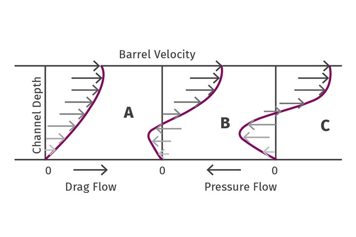
In this design, A shows no head pressure, so all flow is downstream. B shows a degree of head pressure that causes about ¼ pressure flow, so the net flow would be reduced to ¾ of A. C shows more head pressure, so the output is cut nearly in half. (Image: J. Frankland).
In the accompanying illustration, “A” shows no head pressure, so all flow is downstream. “B” shows a degree of head pressure that causes about ¼ pressure flow, so the net flow would be reduced to ¾ of “A.” “C” shows more head pressure, so the output is cut nearly in half. To achieve the best balance of second-stage output, the drag flow should be proportional to the channel depth while the pressure flow is proportional to the cube of the channel depth—and depends heavily on the viscosity. Guesswork on this design feature can be costly, so be sure you have good data or a competent designer if you convert to vented extruders.
When running PCR there is often a need for additional melt filtration due to the likelihood of some contamination; tighter filters or screen packs are typically used to screen out contaminants, which elevates the head pressure. So, if you are changing filtration equipment, the old data for pressure drop through the tooling might not necessarily apply.
ABOUT THE AUTHOR: Jim Frankland is a mechanical engineer who has been involved in all types of extrusion processing for more than 50 years. He is now president of Frankland Plastics Consulting LLC. Contact jim.frankland@comcast.net or (724)651-9196.
Related Content
Is a Gear Pump Right for Your Single-Screw Operation
As with everything else, there are pros and cons, but more of the former. They provide processors higher rates while decreasing the temperature of the extrudate while enabling downgauging.
Read MoreHow To Identify Resin Degradation in Single-Screw Extruders
Degradation can occur in many single-screw extrusion operations, and typically occurs due to minor design flaws in the screw. Here is how to track it down.
Read MoreLet's Take a Deeper Dive on Compression Ratio for Single-Screw Extruders
Two real-world processes illustrate the importance of compression ratio.
Read MoreHow Polymer Melts in Single-Screw Extruders
Understanding how polymer melts in a single-screw extruder could help you optimize your screw design to eliminate defect-causing solid polymer fragments.
Read MoreRead Next
Specifying PCR? Find Answers to These Eight Questions
Understanding how to work with the PCR available today is critical as packaging and other products are being redesigned for circularity.
Read MoreHow to Ensure Reliable Feeder Performance When Handling PCR
Processors are being challenged to incorporate more recycled material into their products. Yet there are both economical and technical obstacles to achieving this objective—feeding among them. The design of your feeding equipment and the advantages that it will offer to your process will be more important than ever.
Read MoreRunning PCR? Optimize Performance & Processability with Stabilizers
Proper stabilization of PCR is vital to enable production of molded and extruded parts to meet brand-owner requirements.
Read More
.jpg;width=70;height=70;mode=crop)
