
How CT Scanning Can Cut Your Product-Development Time
Computed tomography scanning offers molders a wide range of benefits, often saving them hundreds of hours during the processes of mold building, mold tryout, and first- article approval. Here’s what you need to know.
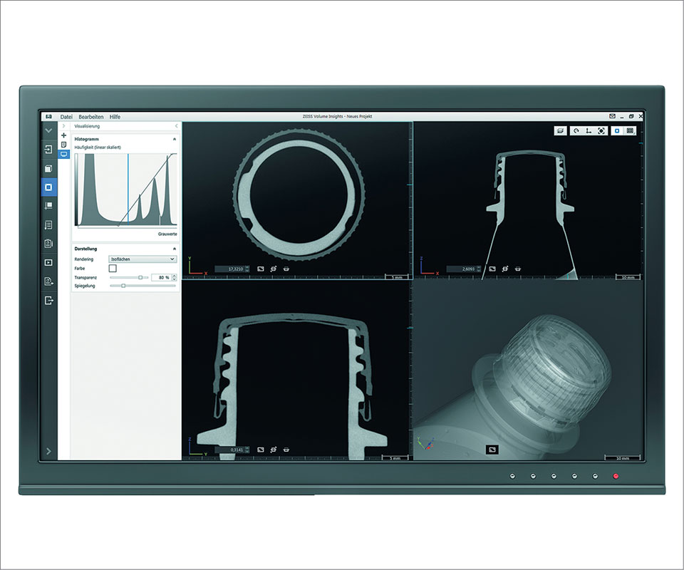
The CT data display using Zeiss NEO insights software shows whether the seal is properly positioned on the bottle.
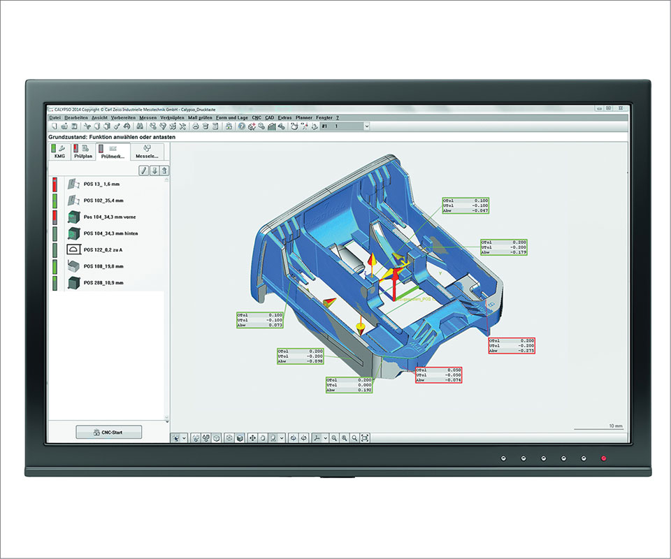
In this application—a button for a seat-belt buckle— the best fit of CT data and CAD data are shown in blue and gray, respectively. Measured values outside tolerance are marked in red.
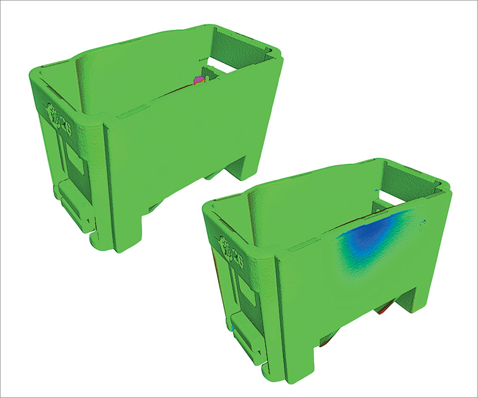
CT scanning enables non-destructive 3D inspection of hidden features. This largely prevents subjective evaluation or operator influences. The scanner can detect material overhang (red in top photo) or display areas of possible dimensional instability (blue in bottom photo).
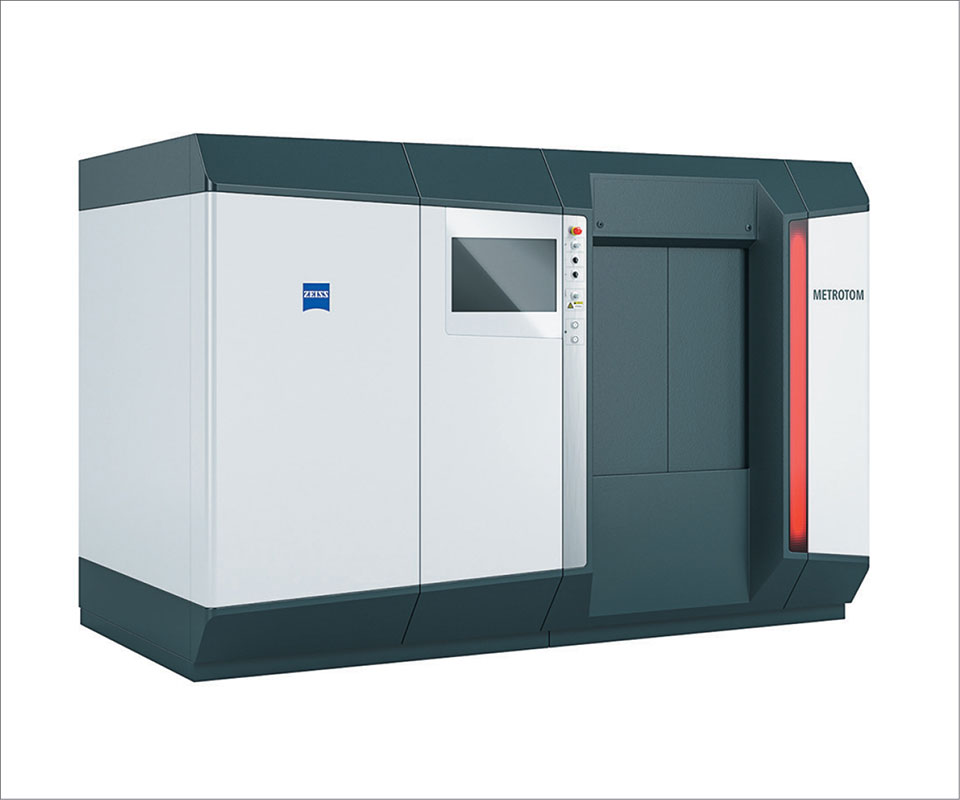
CT x-ray machines like this Zeiss Metrotom system can quickly compare actual measurements of entire components or assemblies with references, graphically highlighting any variances.


One of the biggest challenges molders face is getting parts through first-article inspection (FAI) and into production. Delays in mold verification and performance qualification while waiting for first-article approval often hold up the assembly, delivery, and sale of finished products—a major reason to verify molds and molding processes as quickly as possible. Computed tomography (CT) x-ray scanning can be an invaluable tool for molders to get parts approved for production quickly, troubleshoot production problems faster, and eliminate guesswork.
The first part out of a mold is the critical test of the process and the mold itself. FAI is a process of carefully measuring the test part for conformance, in both shape and size, to the original CAD model. This process can involve multiple pieces of measurement equipment, including CMMs and vision systems, and take dozens, even hundreds, of hours when
checking the geometry of multi-cavity molds.


The entire process of developing satisfactory molds and processes can take weeks or months and strain resources. When simple parts require just a few measurements to be made, CT scanning may not be necessary. But more complex parts have a lot more features to be measured, and this is where CT x-ray scanning really pays off. The more complex the part, the more time CT will save. FAI using CT looks at all prior setups of both critical and non-critical dimensions without adding inspection time. Imagine performing first-article inspection of a complex part requiring more than 1500 features to be measured and doing it in less than an hour.
Modern CT scanning equipment can potentially replace multiple inspection systems and even reduce total equipment cost. And it combines internal and external measurement. In all these ways, it does what no other system can.
HOW CT SCANNING WORKS
CT scanning is a powerful tool for mold designers and for production and quality departments. In medicine, it can be used to find abnormalities in the brain or heart or
fractures in a bone. In industrial process like moldmaking and molding, it is used to find voids and other flaws inside castings and for other kinds of troubleshooting as well.
Here’s how it works: An item to be evaluated is placed on a rotary table and turned as multiple two-dimensional x-ray images are made. The computer joins these images into a detailed three-dimensional image. Traditionally that 3D CT image has been used to identify the presence or absence of specific features or flaws, but not to perform dimensional measurements. CT was essentially a pass/fail imaging process, and for this reason it was not originally focused on extreme dimensional accuracy.
Today, however, enhanced technology allows the capabilities of CT to be combined with the precision of metrology to not just find flaws, but to measure the dimensions, both internal and external, of parts and even assemblies. Sophisticated software combines the functions of CT and CMM (coordinate measuring machine) and lets actual measurements be overlaid with CAD models to see where the two differ, how they differ, and by exactly how much they differ. The enhanced measurement capabilities of CT scanning provide the information designers and engineers need to revise processes or remake molds. It allows faster, more accurate evaluation of molded parts and provides more exact information for revising production processes or re-cutting molds.
With CT scanning, the total time required to evaluate the shape and size of test parts can be slashed from weeks to hours. As a result, the speedy redesign of processes and molds can be based less on intuition and more on hard data and trace- able dimensions. The number of iterations goes down, along with the drain on resources and the cost of final mold production. Molded parts are available sooner, allowing products to go to market faster.
THE PAYOFF FOR MOLDERS
FAI of injection molded parts is an ideal application for CT scanning. In molding, each iteration of measurement and mold modification imposes large costs and significant delay, so anything that increases accuracy and speeds up the process is valuable. Second, plastic of almost any sort is an ideal material to image with X-rays. And with suitable hardware and software, it is equally well suited when the plastic includes metal inserts.
Enhanced CT scanning is like having x-ray vision, making it ideal for non-destructive testing (NDT). It provides the ability to see into a part, and provides dimensional measurement of features and structures without destroying the part. Where CMM touch probing, microscopes, and optical checks are currently utilized, numerous accurate measurements can be taken simultaneously with CT scanning, all in one go. CT scanning quickly provides molders the ability to overlap actual scan data with that of the original CAD model—the “perfect part”—showing user-defined pass/fail criteria, comparing actuals to nominals, and graphically displaying out-of-tolerance variances in easy-to-see colors. The process can be used to reverse-engineer existing products, creating files that can, in turn, generate toolpaths for mold, die, or fixture tooling.
One of the most significant benefits of CT scanning for injection molded parts is it easily
tells how much shrinkage has occurred throughout the part, and graphically illustrates precisely where. It can provide complete data on wall thickness and draft angles to help prevent problems in part ejection. The process will identify part warpage, voids, and porosity to help detect structural integrity issues and possible points of failure. It will quickly find missing features, identify human error, and help troubleshoot assembly issues.
CT scanning gives molders the ability to measure mold wear by easily comparing the CAD model or first-article inspection image with that of the latest production run to determine the degree of mold wear over the course of the product lifecycle. Images of parts produced late in a production run can be graphically compared with displays of earlier measurements.
CT scanning is ideal for analyzing very small parts and very small features that would be difficult or impossible to measure using other technologies. It can be used to scan “micro molds” used for extremely small parts. CT imaging makes small parts look big—easy to see and analyze—where CMMs are unable to gain access to small features and where the probe styli might be bigger than the feature or part itself. CT scanning can often replace vision systems or microscopy. And the entire process is simplified by eliminating the need for traditional fixturing. Parts can be simply set into a piece of foamed polystyrene.
INVESTIGATIVE & FAILURE ANALYSIS
CT x-ray scanning is also ideal for use in failure analysis of systems. It can see how assemblies fit together and how their plastic, rubber, and metal components function together, without the need for disassembling or destroying the object. This allows identification of problems that could not be identified by examining disassembled individual parts.
CT scanning can be used to perform permeability testing to predict vapor or moisture pass-through and measure loss-of-content and shelf-life. This is particularly important in applications like container manufacturing. As container walls get thinner it is important to ensure that they are not so thin that contents are lost through leakage or evaporation, reducing shelf life. Molders of bottle tops for liquids, who need to test for sealing and leakage, can also benefit significantly by using CT scanning.
The technology can help deliver cost savings by helping to determine the amount of plastic material being consumed. The thinner the bottle—without leaks yet durable enough for the application—the greater the savings in material. CT provides the ability to look at overall wall thicknesses of a container, all in one scan. Today, more plastics recycling is being done to save on costs, and CT can be used to analyze how many times plastic can be recycled without losing its integrity.
MEETING FDA REQUIREMENTS
To deal with possible litigation or other regulatory matters, the FDA requires producers of medical products to hold a “first-shot sample” for seven years. The problem is that storing physical parts can require large amounts of space and create a variety of logistical problems. In addition, saved parts can change shape over time. CT scanning provides an unchanging “thumb print” at the time of molding and processing the part. Currently, there are discussions with the FDA about the benefits of saving data files with complete part information rather than the parts themselves. In addition, a modern CT scanning system can generate a variety of FDA-required paper- work, including data on system installation, qualification, and calibration.
ABOUT THE AUTHOR: Barry Rogers recently retired as v.p. of global sales at Haas Automation, a leading builder of machine tools. He has been director of global sales and marketing for Sunnen Products, national sales and marketing manager for Renishaw North America, and general manager of Cincinnati Milacron’s LK CMM div. in Detroit. Rogers recently founded Alpha Strategies, a Chicago-based consulting firm, and is a frequent contributor to TECHSPEX on-line magazine. He also serves as a CT product-management consultant at Carl Zeiss Industrial Metrology LLC, Maple Grove, Minn. Contact: metrology@zeiss.com; zeiss.com/ct.


Related Content

Software Suite Creates Integrated Workflows for Optimizing Moldmaking
Eastec 2025: The HxGN Mould and Die Suite includes VISI, WORNC, NCSIMUL and datanomix tools to provide an integrated workflow from design/engineering to manufacturing and automation.
Read More
Taking Aim at Warpage With Windage
As a last-gasp attempt to salvage a design prone to warpage, CAE Services has developed a hybrid simulation/real-world methodology to ensure better outcomes for when windage is required.
Read More
Front-End Mold Simulation Software Simplifies and Streamlines Design
SimForm by Maya HTT highlights its front-end mold simulation software as a solution for mold designers and tooling managers.
Read MoreRead Next

For PLASTICS' CEO Seaholm, NPE to Shine Light on Sustainability Successes
With advocacy, communication and sustainability as three main pillars, Seaholm leads a trade association to NPE that ‘is more active today than we have ever been.’
Read More
Lead the Conversation, Change the Conversation
Coverage of single-use plastics can be both misleading and demoralizing. Here are 10 tips for changing the perception of the plastics industry at your company and in your community.
Read More