
How Screw Design Can Mitigate Gels in PE Films
Gels are a constant issue in production of PE films using single-screw extruders. Gels can create quality issues via optical flaws, and they can cause the film to break on blown or cast film lines. There are numerous origins for gels, and the mitigation method depends on knowing the gel type.


The term “gel” is commonly used to refer to any small defect that distorts a film product, reducing the quality of the film. There are many types of gels. The most common gels include highly oxidized polymeric materials that appear as brittle black specks; polymeric materials that are crosslinked by an oxidative process, resulting in soft and often discolored gels; highly entangled polymeric materials (such as high-molecular-weight species) that are undispersed and not crosslinked; unmelted resin; filler agglomerates from masterbatches; and a different type of resin or a contaminant such as metal, wood, fibers, insects or dirt.
Identifying the gel type is often difficult and requires specialized equipment and training. Moreover, different gel types require different mitigation techniques. Maintaining gel analyzing equipment and specialized personnel is typically too costly for converters, but most resin suppliers will perform the analysis for their customers.


Screw design can be used to mitigate degradation gels, solid polymer fragments, and highly entangled gels. Obviously, filler agglomerates from masterbatches and foreign materials cannot be mitigated with screw design. This paper will not discuss gels that originate from foreign materials. Degraded resin is obvious in films and it can be an issue in natural-color parts, especially in thin cross-sections. This article will provide screw-design options to mitigate resin-degradation gels, highly entangled gels in PE resins, and solid polymer fragments.
Solid Polymer Fragments
Solid polymer fragments can occur in almost all resin extrusions when the solids conveying rate and the metering rate exceed the melting capacity of the screw. Typically, when the extruder screw speed is doubled, the solids conveying rate and the metering rate double, but the melting rate only increases by a factor of 1.4. Thus, the flow rate increases faster with screw speed than does the melting capacity.
For example, a melting-capacity experiment was performed using a 63.5-mm diam. extruder with a screw that was single flighted with a metering channel depth of 3.18 mm and a compression ratio of 2.8. If all material is melted early in the extruder, the extrudate will be nearly uniform and black, as shown in Fig. 1, at screw speeds less than 60 rpm. As the screw speed is increased, a speed is reached where a significant amount of solid polymer fragments is discharged. As the screw speed is increased further, a larger amount of solid polymer fragments is discharged from the extruder, as shown by the large, white solid fragments in Fig. 1, at a screw speed of 150 rpm.
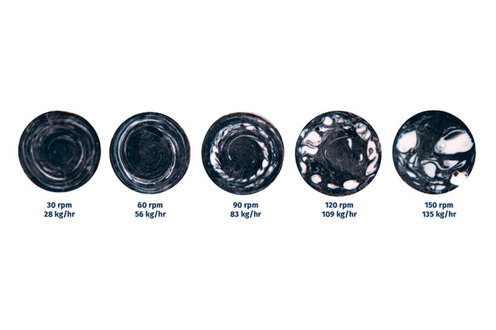
FIG 1 Cross-sectional views of extrudate samples of a white-pigmented ABS with a black color concentrate at a letdown ratio of 100:1 for a melting experiment. The large, round white regions of the cross-sections at screw speeds of 90 rpm and higher are solid particles that discharged with the extrudate. (All images: Dow)
There are several methods for mitigating solid polymer fragments in extrudates. The first method and most obvious from Fig. 1 is to slow down the screw speed and the output rate to a level that reduces the solid fragments in the extrudate. This method often works well as a diagnostic tool but operating at low rates is not economical for a converter. A second method, and the best option, is to design and fabricate a new screw with a Maddock-type mixer near the discharge end of the screw. Maddock mixers are well suited for trapping, melting and then dispersing solid polymer fragments. The third option is to build a new screw that has a shallower metering section and a Maddock mixer. The shallower metering section will operate at a lower specific rate and increase the melting capacity relative to the solids conveying rate and metering rate. The specific rate is simply the rate divided by the screw speed: kg/(hr-rpm).
Degradation Gels
Degraded resin can form in regions of the screw that are stagnant or have extremely long residence times. Antioxidants can slow the process down, but once they are consumed degradation will occur. High temperatures and the presence of atmospheric oxygen accelerate the degradation process. Once degraded resin forms in the stagnant regions, small process perturbations can cause the degraded resin to separate from the screw and flow out with the extrudate, creating gels in the final product.
There are numerous screw-design defects that can cause the resin to stagnate, degrade, and then contaminate the product, but only the three most common defects will be discussed here. These defects include the designs of barrier melting sections, Maddock mixers, and flight radii in metering channels.
Degraded resin can form in regions of the screw that are stagnant or have extremely long residence times.
The screw-design defect that causes the highest level of degradation gels in PE products is a poor design of an entry to a barrier melting section. In this design, the solids-conveying channel compacts the PE pellets via the increasing temperature and pressure in the channel. Next, the solid bed must flow past the entry to the barrier melting section and into the solids-melting channel. This pathway can be very restrictive in some designs. The restriction occurs because of the introduction of the barrier melting flight that decreases the channel width available for solids flow by up to 30%.
Several designs have mitigated this restriction by increasing the lead length in the barrier section. If the flow path is highly restrictive, it can control the specific rate of the process rather than the metering channel as designed. That is, the screw will be designed to run at full specific rate, but the restriction allows the specific rate to be only about half that. This causes some of the channels downstream from the restriction to operate partially filled. Partially filled channels will typically cause resin to degrade.
Partially filled channels in the metering section of the screw will cause the resin to degrade, as shown in Fig. 2. For this case, the main flow of resin is clear and at the pushing side of the channel. At the start with a clean screw, the trailing side is void of resin. During operation, some of the clear resin migrates to the void region and then rides on the screw for extended periods of time. Depending on the PE resin type, degradation will occur in hours to days. Once the degraded resin is formed, a small process instability will occur, causing some of the degraded resin to separate from the screw. The degraded resin can be broken up in the downstream sections of the screw, causing a gel shower in the extrudate and product.
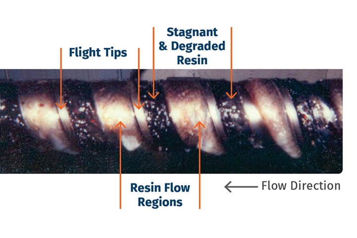
FIG 2 Photograph of the main flow and stagnant regions of a barrier screw running LDPE. The white polymer is the main flow region, and the dark material is degraded resin in the stagnant region.
There are several ways to eliminate the restriction at the entry to the barrier melting section. The easiest method is to design the screw with the lead length equal to the barrel diameter in the solids-conveying section, and then transition to a lead length that is about 1.25 times the diameter in the barrier melting section. The longer lead length in the barrier section will create a larger distance between the main flights, allowing additional width for the introduction of the melt-separation (barrier) flight. Several proprietary designs are used in this type of construction, but restrictions can still occur.
Secondly, the restriction can be simply removed by not using a barrier melting section—i.e., a simple helical screw with a Maddock mixer. This type of screw works well for extruder screws with diameters less than about 80 mm, although the benefits of a barrier melting section are also given up. Other methods to reduce the restriction at the entry are available, but they are beyond the scope of this article.
Resin degradation can also occur for improperly designed flutes of Maddock mixers. Several screw manufacturers design screws with Maddock mixer flutes that are too deep. This design is used to reduce the pressure consumption through the device. Here the flutes are cut very deep, creating flat edges near the flight tips. This design can cause the resin to degrade, as shown in Fig. 3. The degraded resin is the brown-tinted material in the photograph.
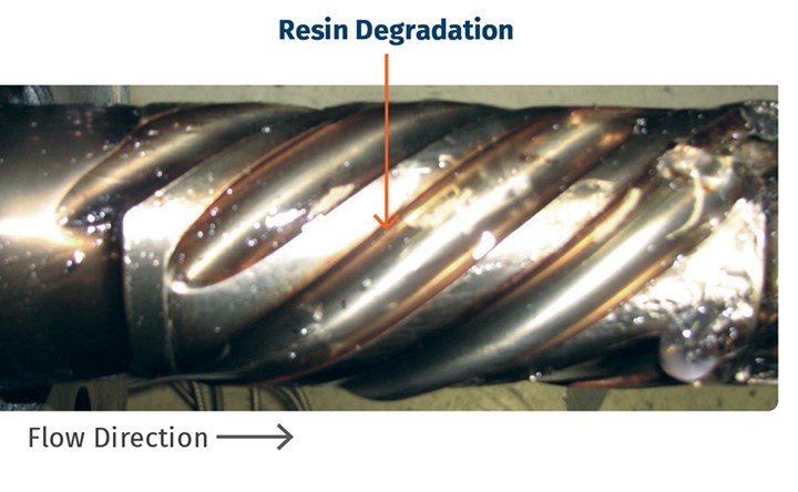
FIG 3 Photograph of a Maddock mixer with flutes that are too deep, causing resin degradation at the leading and trailing sides of the flutes.
A low level of background gels can occur if the flight radii in the metering section are too small.
A deep flute construction is shown in Fig. 4a. The flutes on this mixer were created using a ball end mill. The mill cut into the metal stock to a depth larger than half the diameter of the ball mill (Fig. 4b). This creates a flat edge parallel to the radial direction of the screw. This deep channel and the flat edges are the main root causes for resin degradation. A better design is shown in Fig. 4c where the flute depth is set to half of the flute width. Here the ball end mill was used to cut into the metal stock up to the equator of the mill, as shown in Fig. 4d.
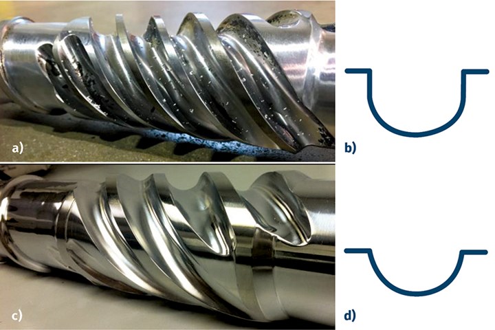
FIG 4 Effective and poor Maddock mixer designs: a) and b) show poor design with very deep flutes; c) and d) show an effective design with flutes no deeper than half the width.
A low level of background gels can occur if the flight radii in the metering section are too small. Small flight radii create recirculation regions known as Moffatt eddies. These eddies have very long residence times. The long residence times and often the presence of atmospheric oxygen cause the resin to degrade. Small process instabilities will cause a small amount of the degraded resin to separate from the screw and create a background level of defects in the film product. Resin degradation at the flight radii is shown in Fig. 5.
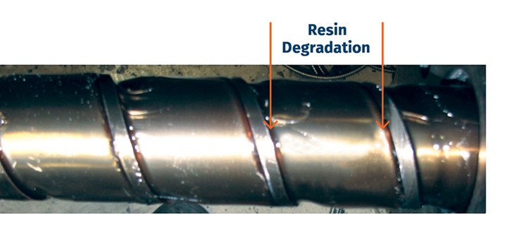
FIG 5 Photograph of a metering section, showing PE degradation at the flight radii. The flight radii were small and about 50% of the channel depth.
Small flight radii are the industry standard for commercial screws. They are easier to fabricate and guarantee that slight variations in the manufacturing process maintains a constant flight width. Radii that are larger than the local channel depth are harder to fabricate and can cause the flight width to vary. A typical flight radius for most commercial screws is shown by the small radius R1 in Fig. 6. This radius is about 50% of the local channel depth, and it will likely cause resin degradation in most PE resins. The large radius R2, however, is about 1.5 times the depth of the channel, and it will likely not cause resin degradation. Processors should request that the radii in the metering channel be specified at 1.5 times the depth when ordering new screws.
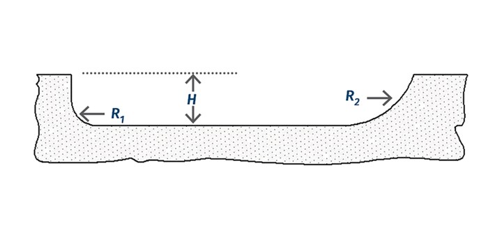
FIG 6 Schematic of small (R1) and large (R2) flight radii.
Highly Entangled (Unmixed) Gels
Unmixed gels are highly entangled species that are molten when they are discharged from the die but solidify first upon cooling to produce a gel that appears as a solid polymer fragment. These types of gels are typically about 0.5 mm in diameter and are easily removed from an extrusion process by subjecting all molten resin to a one-time, high level of stress near the discharge of the screw. This stress is easily applied using a Maddock mixer with a relatively tight clearance on the mixing flight.
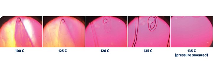
FIG 7 Photographs of an unmixed gel at select temperatures using a hot-stage microscope. The highly entangled gel and matrix material melted at about 135 C. When the gel was smeared by moving the glass cover slip, the stress was enough to disentangle the polymer chains such that the gel would not reappear upon cooling.
Highly entangled gels are identified using hot-stage microscopy. First, the gels are isolated from the film, placed on a microscope slide, and covered with silicone oil and a glass cover slip. Next, the stage temperature is slowly increased to identify the melting temperature of the matrix resin and the gel, as shown in Fig. 7. When the gel in Fig. 7 is stressed at 135 C by pushing on the cover slip with a dental tool, the gel is disentangled. When the sample is cooled, the gel does not reappear. Thus, the applied stress disentangled the gel.
Processors should request that the radii in the metering channel be specified at 1.5 times the depth when ordering new screws.
Since highly entangled gels can be disentangled with stress, these gels can be easily dispersed into the matrix material using a Maddock mixer positioned near the end of the screw. The stress level required to disperse a highly entangled gel depends on the resin and the level of chain entanglement. In past experiences, the stress level required to disperse entangled gels is about 100 to 200 kPa. The undercut on the mixing flight of the Maddock mixer can be set such that this level of stress is obtained.
A cross-sectional view of a Maddock mixer is provided in Fig. 8. The wiping flight extends to the barrel wall and within the normal flight clearance (l). The mixing flight is undercut past the wiping flight by a distance of u. Thus, the gap between the barrel wall and the land of the mixing flight is (u + l).
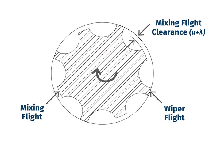
FIG 8 Cross-sectional view of a Maddock mixer showing the wiper flight and the mixing flight.
The shear stress that the material experiences for flow across the mixing flight of the Maddock mixer can be estimated using the two equations below. The shear-stress level is responsible for breaking up the entangled species.
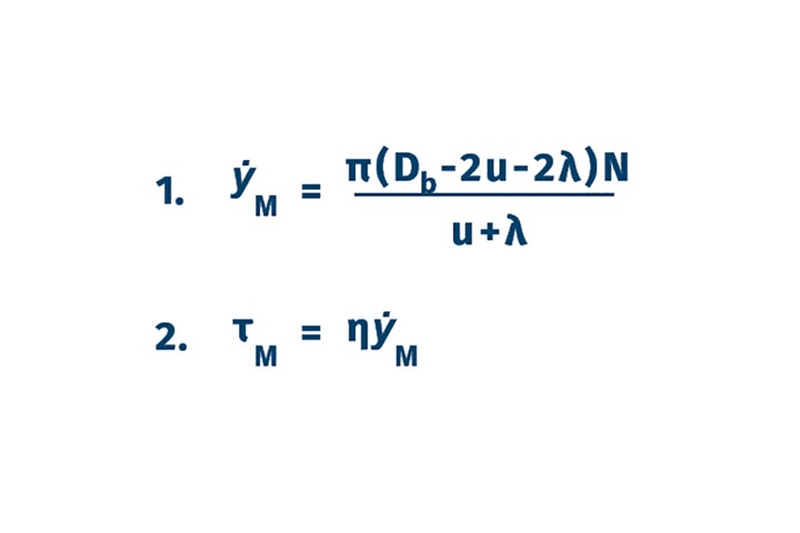
where γ ̇M is the average shear rate for flow over the mixing flight in 1/sec; N is the screw rotation rate in revolutions/sec; h is the shear viscosity at the temperature of the mixing process and at shear rate γ ̇M ; Db is the barrel diameter; and τM is the shear stress that the material will experience in flow over the mixing flight.
Many screw designers set the mixer undercut at 1 to 1.5% of the diameter of the extruder. This level is typically enough to homogenize colorants and additives and trap and disperse solid polymer fragments; but in many cases the shear stress that is generated is not enough to mitigate highly entangled gels. For many PE resins, an undercut of about 0.5% of the diameter is needed to obtain a shear stress of 100 to 200 kPa.
ABOUT THE AUTHOR: Mark A. Spalding is a Fellow in Packaging & Specialty Plastics and Hydrocarbons R&D at Dow, Inc. in Midland, Mich. During his 37 years at Dow, he has focused on the development, design, and troubleshooting of polymer processes, especially in single-screw extrusion. He co-authored Analyzing and Troubleshooting Single-Screw Extruders with Gregory Campbell. Contact: 989-636-9849; maspalding@dow.com; dow.com.


Related Content

How Much L/D Do You Really Need?
Just like selecting the extruder size and drive combination, the L/D should be carefully evaluated.
Read More
The Importance of Viscosity in Melting
The calculations required to determine the right melt temperature for each polymer are complicated. Knowing the power-law coefficient and the consistency index of the polymer you run might prove useful.
Read More
Extruder Alignment: Important, but Only Half the Equation
The other half? Aligning and supporting downstream equipment. Here are best practices.
Read More
Understanding Melting in Single-Screw Extruders
You can better visualize the melting process by “flipping” the observation point so that the barrel appears to be turning clockwise around a stationary screw.
Read MoreRead Next

Reducing Low-Level Background Gels in PE Film
While considered acceptable in many cases, they need not be tolerated and are usually attributable to minor screw-design flaws. Here’s some advice on what to do about them.
Read More
Solve Five Common Problems in Blown Film Coextrusion
The blown film industry has evolved from monolayer film structures to multilayer ones for a variety of food and non-food packaging applications. Here are typical problems with these structures and tips on how to solve them.
Read More
Solving Gels in Thin Film, Tubing Extrusion
Gels are a common quality problem in thin film and tubing extrusion. To solve them, learn from where they came.
Read More