


The blown film industry has evolved from monolayer film structures to multilayer ones for a variety of food and non-food packaging applications. Depending on the product requirements, a wide array of materials can be incorporated into the film structure to attain desired properties.
A process engineer working in this field must have a fundamental understanding of polymer rheology in order to properly specify equipment and select process conditions. Without sufficiently understanding polymer properties, unwanted layer interactions can occur during processing, which may lead to defects in the film.


Rheology is the study of the deformation and flow of a material. The extent of deformation and flow a material experiences is dictated by its rheological properties. For a polymer, these properties are dependent on physical characteristics such as molecular weight (MW), molecular-weight distribution (MWD), long-chain branching (LCB) and melting temperature. In blown film coextrusion, the most important rheological properties to be considered are shear viscosity, viscous dissipation, and elongational viscosity.
Shear viscosity is a measure of the resistance a material experiences to shear flow and is impacted by both shear stress and shear rate. Shear stress is defined as the force per unit area applied to a material, whereas shear rate is defined as the rate of deformation of a material.
Polymers are non-Newtonian fluids, and therefore their viscosity does not remain constant with varying shear rates. Generally, the shear viscosity of a polymer will decrease with increasing shear rate, a behavior known as shear thinning. The rate at which a polymer shear thins determines how it is processed. For example, a highly branched polymer is more shear sensitive than a linear polymer, and will therefore experience a more rapid decrease in shear viscosity at higher shear rates. Processing highly viscous materials will result in increased melt temperatures, increased head pressures, and will require more applied torque from the extruder.
As a polymer is sheared, the chain entanglements within its molecular structure begin to unravel. This disentanglement process generates heat, a phenomenon known as viscous dissipation. Viscous dissipation is proportional to both the applied shear rate and polymer viscosity, meaning that an increase in polymer viscosity and/or shear rate will result in an increase in melt temperature. This phenomenon creates a temperature gradient between the extruder barrel and the melt. If not properly accounted for, this increase in melt temperature may result in the overheating and degradation of the polymer.
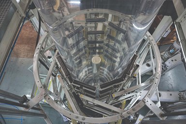
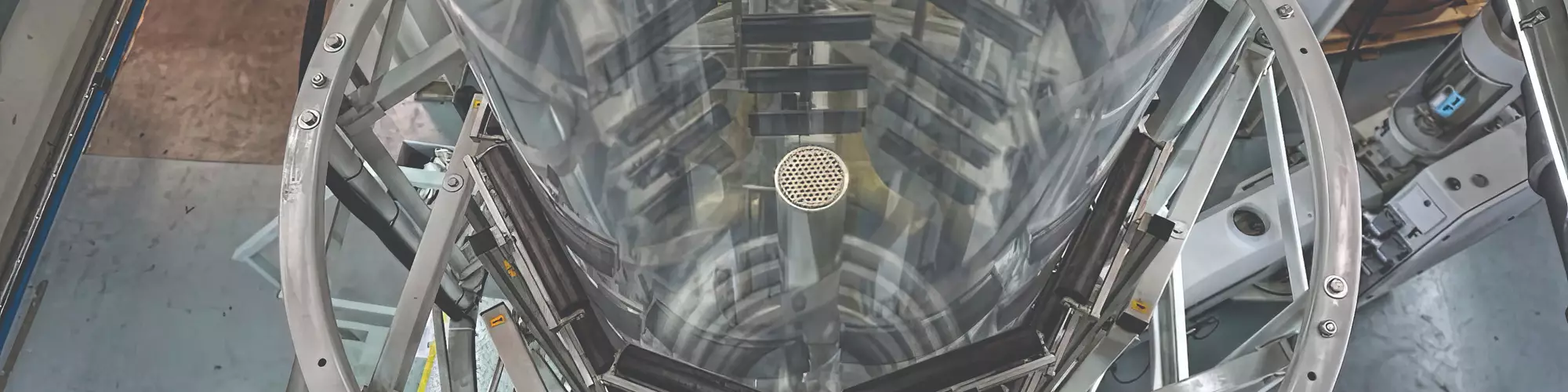
Blown film processors continue to add layers to structures to improve properties and performance. Shown here is a nine-layer line from Macro.
Elongational viscosity is defined as a material’s resistance to stretching. Similar to shear viscosity, the elongational viscosity of a polymer will depend on its molecular structure. A polymer with a high degree of LCB will have a high elongational viscosity because the long branches become entangled among themselves during extension. The maximum tension that can be applied to a melt without experiencing material fracture is known as melt strength. A material with a higher elongational viscosity will have a higher melt strength. The melt strength of a polymer will impact the resulting stability of the bubble being formed in blown film extrusion. A material with lower melt strength is more difficult to process because it will fracture more easily while being stretched during bubble formation.
Common Problems and Troubleshooting Techniques
Although producing multilayer films is advantageous and provides opportunity for improvements in film properties, the increased structural complexity creates new challenges for process engineers. There are four key factors to consider in order to successfully produce a multilayer film: 1) polymer selection, 2) process equipment design, 3) layer arrangement, and 4) process conditions. Problems in blown film coextrusion arise when insufficient consideration is given to one or more of these factors. Five common problems associated with blown film coextrusion, along with troubleshooting techniques for each, are detailed below.
1. Bubble Instability: The term bubble instability encompasses many different types of issues related to the stability of the extruded bubble. The main issues include bubble breaks, strain hardening, unstable frost line, and bubble fluttering.
Bubble Breaks: A bubble break occurs when molten material exiting the die is overstretched, resulting in a break in the bubble structure. This can occur when the melt strength of the extruded material is insufficient for the selected blow-up ratio (BUR). To avoid this problem, resin selection can be modified to incorporate a higher-melt-strength material into the film structure to improve the overall melt strength. An example of this is incorporating low-density polyethylene (LDPE) into a linear low-density polyethylene (LLDPE) film to increase its overall melt strength.
Strain Hardening: Strain hardening occurs when molten polymer is rapidly stretched in the machine direction (MD) and stiffens as a result. This causes fluctuations in internal bubble pressure and bubble width. This issue can be prevented by reducing the drawdown ratio. Another solution is to modify the resin selection to decrease the overall elongational viscosity of the film, allowing the film to stretch more in the MD without experiencing any strain hardening.
Unstable Frost Line: In a stable process, the frost line will remain at a constant height above the die and is controlled by the cooling rate, die throughput, and film-thickness uniformity. When a process becomes unstable, the position of the frost line will become unstable as well. One cause of this instability is a non-uniform temperature profile in the extrudate.
Variations in melt temperature may stem from improper screw design for the selected resin, a worn screw, or a failure in a heater or thermocouple. Melt temperatures should be taken for each stream prior to merging to determine which melt layer is the source of the temperature variation. Once located, the screw can be removed and inspected for polymer degradation and screw abrasion. All heaters and thermocouples should also be checked for functionality.
Another common cause of an unstable frost line is a blockage in the die. A non-uniform die throughput may be due to a buildup of degraded material in the die. To avoid this, the die should be inspected for material buildup periodically and cleaned if necessary.
Bubble Fluttering: Bubble fluttering initiates below the frost line and appears as linear marks on the bubble surface in the transverse direction (TD). This fluttering is caused by high air velocity coming from the air ring. Decreasing blower speeds or adjusting air-ring components to reduce the air flow along the bubble surface will prevent bubble fluttering. However, reducing air flow will subsequently decrease the cooling efficiency of the air ring, which may then cause the frost line to drift away from the die, leading to new problems. To avoid this situation, resin selection can be optimized to reduce the overall melt viscosity of the extrudate and decrease the overall melt temperature.
2. Gauge Variation: In blown film coextrusion, it is inevitable to have some degree of gauge variation in the film, typically in the TD. An example of a gauge profile for a film with a low degree of gauge variation can be seen in Fig. 1a. However, if unexpected issues begin to arise during processing, the degree of gauge variation can increase. There are a few different issues that may lead to increased gauge variation, and determining the cause of the issue can be done by examining the shape of the gauge profile for the bubble.
Misaligned Die: A common source of gauge variation is a misaligned die gap. A misaligned die will result in a non-uniform flow distribution of material leaving the die. A common indicator of a misaligned die is an offset gauge profile, like the one shown in Fig. 1b. To correct this, the die gap should be checked for uniformity along the circumference. If misaligned, the die can be recentered using the die-adjustment bolts.
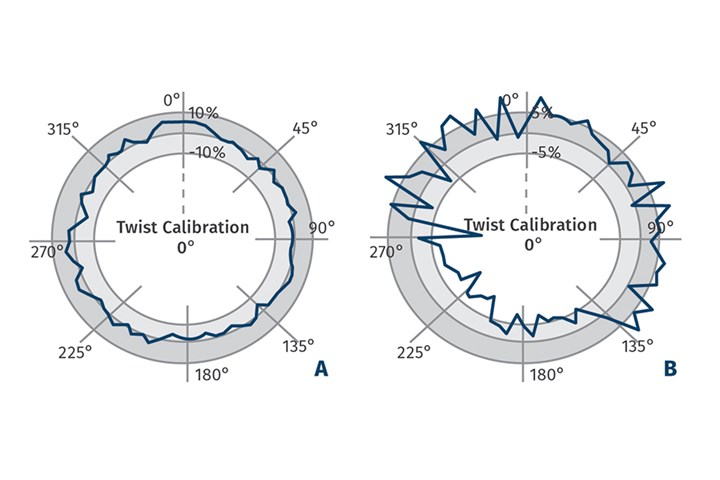
FIG 1 Examples of gauge plots for film samples experiencing: A) minimal gauge variation; and B) offset gauge variation.
Non-Uniform Air-Ring Cooling: Poor or non-uniform air flow coming from the air ring will result in non-uniform film cooling, which will impact the drawdown ratio of the film. This can result in portions of film being stretched more than others, which may lead to gauge variation. To avoid this issue, the air channels in the air ring should be inspected and cleaned periodically to remove any impurities that may cause air-flow disturbances. The air ring should also be checked to confirm it is properly centered on the die.
Non-Uniform Melt Temperature: Non-uniform melt temperature will result in variable bubble cooling rates and die throughputs. A telling sign of a non-uniform melt temperature is a sinusoidal gauge profile. The formation of this sinusoidal gauge variation is related to the flow of a material having a non-uniform melt temperature through a die, a phenomenon known as port lines. As previously described, variations in melt temperature are likely caused by an improperly designed or worn screw.
3. Interfacial Instability: The term interfacial instability refers to instabilities occurring at the interface between two layers. The stability of the interface will depend on factors such as material properties, process conditions, and equipment design characteristics. Three known types of interfacial instability that may arise during blown film coextrusion.
Zig-Zag Interfacial Instability: This form of instability occurs when an interface experiences excessive shear stress, resulting in the formation of “zig-zag” distortions along the film surface in the TD direction. An image of this instability is shown in Fig. 2.
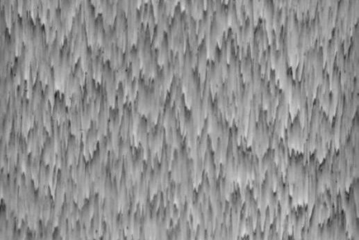
FIG 2 Image of a polymer interface experiencing high shear and exhibiting zig-zag interfacial instability. (Source: Zatloukal, M., Kopytko, W., Vlcek, J., and Saha, P., SPE ANTEC 2005)
There are a few known causes of the zig-zag instability. The first is differences in shear viscosity between the materials creating the interface. If the materials have distinctly different shear viscosities, the individual layers will experience differing shear rates at an applied shear stress, causing the zig-zag deformation to appear. This can be mitigated by selecting materials with similar shear viscosities (if possible) to create the interface.
The second cause is an improper layer ratio. If the layer ratio chosen is such that the interface is too close to the die wall, the excessive shear stress will trigger the deformation. To prevent this, the outer layer thickness can be increased to shift the interface away from the wall and reduce the shear stress applied onto it.
The third cause is an improper die design. When designing a die, it is important to properly optimize fluid channels to create a uniform velocity profile throughout the die. Improper die design may lead to the formation of high-shear points and a non-uniform velocity profile, resulting in this instability.
Wave Interfacial Instability: This form of instability is caused by non-uniform elongational deformation occurring at an interface between two materials, resulting in wave-like patterns forming along the bubble surface as it is extruded from the die. An image of this instability can be seen in Fig. 3. The elongational deformation causing this instability has been found to occur from two known sources. The first is associated with an improper layer ratio. If one of the combining layers of the structure is too thin, it will experience more acceleration at the merge point within the die, resulting in a higher rate of elongational deformation in that layer. Layer ratios should be adjusted to allow for a more uniform velocity profile to form downstream of the merge point.
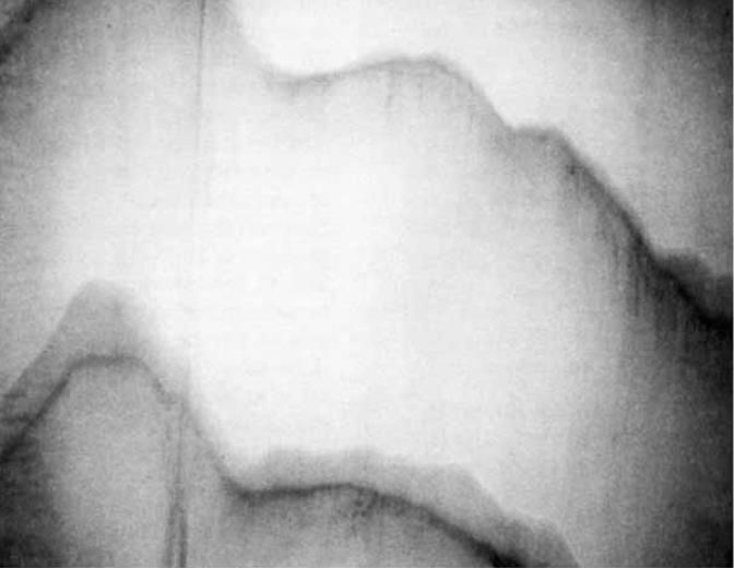
FIG 3 Image of a polymer interface exhibiting wave interfacial instability. (Source: Tzoganakis, C., and Perdikoulias, J., Polymer Engineering & Science, Vol. 40, p. 1056, 2000)
The second source is a difference in the elongational viscosities of the materials creating the interface. Two materials with differing elongational viscosities experiencing the same elongational force will deform at different rates. If possible, materials having similar elongational properties should be chosen to create the interface.
Reactive Interfacial Instability: A reactive interface may form during the coextrusion of a multilayer structure consisting of a polar barrier resin and a tie layer. Barrier resins are typically coextruded together with layers of polyolefin resin. These structures typically require a tie layer between them to improve their adhesion to one another. Tie layers are polymers consisting of both polar and nonpolar end groups. Occasionally, unwanted chemical reactions may occur between the polar end group of the tie layer and the polar barrier resin, creating an unstable interface. The result of these reactions is a reduction in optical clarity and a film with a more grainy appearance.
An example of this instability is an interface between EVOH and a tie layer with a maleic anhydride (MA) functional group. Unwanted reactions may occur between the MA of the tie layer and hydroxyl groups along the EVOH chain. A visual example of this instability is shown in Fig. 4, which compares a PP/EVOH multilayer film with no tie layer (Fig. 4a) and a MA tie layer (Fig. 4b) coextruded at the same conditions. The addition of the MA tie layer resulted in a drastic deterioration of optical film clarity, caused by unwanted interactions occurring at the interface between the EVOH and the MA tie layer. To prevent this from occurring, the tie layer can be replaced with one consisting of a different functional end group.
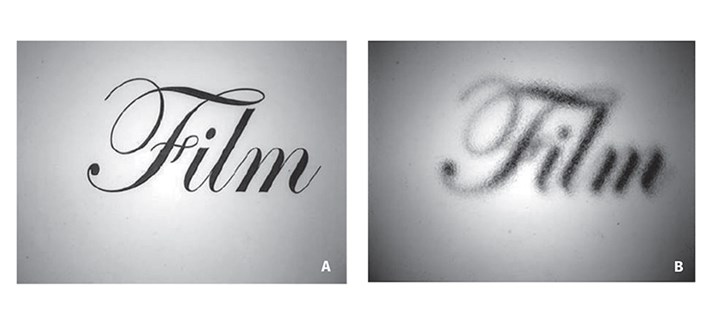
FIG 4 Comparison of optical clarity for: A) a nonreactive PP/PP/EVOH/PP/PP film; and B) a reactive PP/PP-MA/EVOH/PP-MA/PP film. (Source: Bondon, A., Lamnawar, K., and Abderrahim, M., Polymer Engineering & Science, Vol. 55, p. 2542, 2015)
4. Gels: The term gel is commonly used to refer to any form of small defect that creates an optical distortion in the final film. Gels are problematic because not only do they create an optical distortion, they can also reduce the mechanical properties of the film. Gels can be divided into three main categories: unmelted resin, degraded materials, and foreign contaminants.
Unmelted Resin: Unmelted resin is a common type of gel that is typically observed at high extruder throughputs. They are a result of non-uniform melting caused by low-shear regions located within the extruder. To determine if a gel is unmelted resin, heat the gel above its melting temperature, and then let it cool back down. If the gel does not re-appear after cooling, it was unmelted resin. If unmelted resin is present in the film, the extruder screw should be examined and redesigned to minimize the presence of low-shear zones.
Degraded Materials: Material degradation can occur during extrusion if a polymer is exposed to high levels of energy for an extended period of time. These conditions lead to the formation of highly oxidized or crosslinked materials, which appear as gels in the film. Typically these gels are not present immediately after startup. They appear on the film over time as the degraded polymer accumulates within the process.
Highly oxidized gels appear as brittle black specks and can be identified by their fluorescence under UV light. Figure 5 shows an image of a highly oxidized gel taken under polarized light, and an image of the gel fluorescence under UV light. Crosslinked gels have a dark brown appearance and consist of oxidized material, however the degree of oxidation is too low to cause fluorescence under UV light.
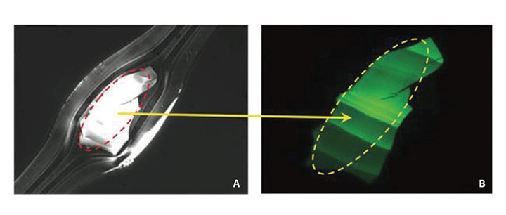
FIG 5 Images of a highly oxidized gel in a multilayer film under A) polarized light and B) UV light. (Source: Campbell, G., Spalding, G., Analyzing and Troubleshooting Single-Screw Extruders, Hanser, Vol. 1, p. 486, 2013)
Crosslinked gels are sometimes mistaken for highly entangled resin. To distinguish between the two, heat the gel up above its melting temperature, apply a stress on it to break it up, and allow for it to cool. If the gel shape reappears after cooling, the material is crosslinked and not highly entangled. To determine the source of the degraded material, the extruder screw should be removed after operation without purging. Once the source of the degradation is identified, the screw design can be optimized in that region to minimize the stagnation and low shear forces present.
Foreign Contaminants: Occasionally, foreign contaminants may gain entry into the process. Foreign contaminants typically enter the extruder with the main feedstock through the hopper, and can range from clothing fibers to foreign polymer resin. If the gel is found to have a distinctly different melting temperature than the feedstock resin, or a very irregular shape (such as a fibril), it is likely a foreign contaminant. To avoid these gels, the hopper should always be properly cleaned, and the virgin feedstock container should be enclosed to prevent any foreign objects from being mixed in.
5. Film Curling: Film curling is a defect observed with multilayer structures consisting of materials having varying degrees of crystallinity. This defect forms during the cooling of the molten film and causes the film to roll up on itself. Film curling is related to two issues: differences in material properties (i.e. melting point, degree of crystallinity) and improper layer arrangement.
A common example of film curling is shown in Fig. 6, which illustrates a three-layer film consisting of polyethylene (PE), nylon (PA) and a tie layer. As the multilayer film exits the die, all layers are molten and the film begins to cool. As it cools, the nylon layer crystallizes and becomes rigid while the PE layer shrinks, as it is still molten. Once the temperature decreases below the melting temperature of PE, it starts to become rigid as well. However, at this point the nylon is already crystallized and cannot shrink further, causing the PE to curl away from it during solidification.
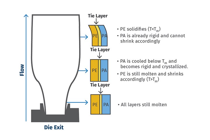
FIG 6 Film curling example of a three-layer blown film coextrusion line consisting of PE, PA, and a tie layer.
One method to prevent film curling is rapidly cooling the film to prevent crystallization. As opposed to using air to cool the film, the film can be extruded directly into a water bath for rapid cooling. This allows for materials with differing crystallization rates to be coextruded without the film exhibiting any curling. Another possible solution is to optimize the structure of the multilayer film.
For example, modifying the structure of a PE/tie/PA film, which is likely to curl, to PE/tie/PA/tie/PE/tie/PA. The additional layers in the new film increase the overall mass of the film which will mitigate the extent of curling that the film experiences.
About the Authors: Tomislav Ivancic is a process-engineering technologist at Macro Engineering and Technology Inc., currently involved in R&D and rheological process modeling. He received both his MASc. and B.Eng in chemical engineering from McMaster University, with a specialization in polymer materials and processing. Contact: 905-507-9000; tivancic@macroeng.com; macroeng.com.
Dr. Karen Xiao is vp of technology at Macro Engineering. She has almost 25 years of experience in the industry in both equipment and film manufacturing. Prior to joining Macro in 2020, she was the extrusion technology leader for Celgard LLC, an Asahi Kasei company, responsible for battery-separator film development for nine years. Xiao is also on the Board of Directors of the SPE Extrusion Div., having served as the Division Chair and Technical Program Chair. She was elected Fellow of SPE in 2016. She has over 50 publications and six pending and granted patents in film extrusion. Contact: kxiao@macroeng.com.


Related Content

Film Extrusion: Boost Mechanical Properties and Rate of Composting by Blending Amorphous PHA into PLA
A unique amorphous PHA has been shown to enhance the mechanical performance and accelerate the biodegradation of other compostable polymers PLA in blown film.
Read More
Breaking News From NPE2024
Here is a firsthand report of news in injection molding, extrusion, blow molding and recycling not previously covered.
Read More
Reduce Downtime and Scrap in the Blown Film Industry
The blown film sector now benefits from a tailored solution developed by Chem-Trend to preserve integrity of the bubble.
Read More
Use a Process Assessment to Determine the Benefits of Screw-Design Modification
This type of analysis will provide the converter with a clear picture of whether changes to the screw could provide economic gains through increased rate, yield, and quality.
Read MoreRead Next

How to Use 'Mapping' to Troubleshoot Blown Film Problems
Three real-world case studies show how processors solved common problems in blown film via the mapping technique.
Read More
Get Rid of Wrinkles In Blown Film
The biggest cause of wrinkles in the blown film process is instability of the bubble between the air ring and where the bubble reaches full diameter.
Read More
Take These Steps To Maintain Efficiency Of Your IBC
The overall performance of a blown film line depends on a properly tuned and maintained IBC control system. Follow these preventive-maintenance tips to keep your system running smoothly.
Read More