Extruder Alignment: Important, but Only Half the Equation
The other half? Aligning and supporting downstream equipment. Here are best practices.
I wrote about the importance of extruder barrel alignment and how it should be done several years ago, but aligning the extruder barrel is not the whole solution. The downstream equipment must also be aligned and supported properly to maintain the properly aligned barrel.
After breaking a screw, a client of mine brought in a competent company to align the barrel. But the new screw lasted all of three weeks. Upon startup one day, the screw broke, and in the process also heavily damaged the barrel, requiring its replacement as well.
I was asked to be there for the startup with the new barrel and screw. The extruder was started and I immediately heard a grinding sound and noticed a large fluctuation of the drive amps. I had the extruder shut down immediately and asked how they had lined up the downstream components to the extruder.
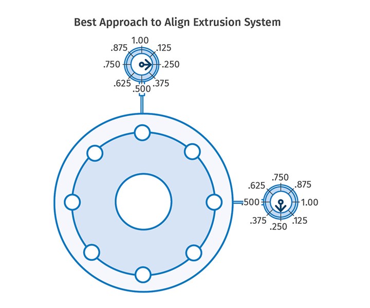
The best approach is to complete the barrel alignment using optical- or laser-alignment equipment. Also put dial indicators, as shown here, anchored to an independent support to maintain that alignment as the downstream equipment is attached and heated up.
The screen changer was a double-piston type and weighed about 4000 lb. Although it was supported in a stand on rubber casters, the floor was very uneven, and the installers had simply pushed the flanges close together and then used the bolts to pull the screen changer into its position on the barrel with no regard for its effect on the barrel alignment.
Next was the melt pump, which weighed about 1750 lb without the drive motor and reducer. Again, the unit was on a stand with rubber casters, but the installers had once more made no effort to align it. Instead, they simply pulled it into place against the screen changer and used the bolts to draw it into position. Finally the die was coupled to the melt pump with the same procedure on a similar stand.
I instrumented the extruder barrel flange with two dial indicators mounted at 90° to one another, as shown in the accompanying illustration. As the screen changer was loosened from the barrel, the vertical dial indicator showed a rise in the barrel of 0.255 in. and the horizontal indicator showed a lateral movement of slightly over 0.100 in.
Barrel alignment is not just a matter of lining up the barrel itself but maintaining that alignment after the whole system is assembled.
Obviously that totally destroyed the alignment of the barrel to the drive quill, and the resultant bending and repositioning of the barrel caused severe contact between the screw and the barrel bore. The point here is that barrel alignment is not just a matter of lining up the barrel itself but maintaining that alignment after the whole system is assembled.
The best approach is to complete the barrel alignment using optical- or laser-alignment equipment, then put dial indicators anchored to an independent support to maintain that alignment as the downstream equipment is attached and heated up. Not only will the mechanical attachment of downstream equipment affect the alignment, but the heating-up phase is also important, as the downstream components and the barrel itself can change position substantially as thermal expansion affects the entire assembly. The only way to determine if the alignment is being altered when completing assembly of the line is to instrument the barrel flange.
The only way to determine if the alignment is being altered when completing assembly of the line is to instrument the barrel flange.
This is a very simple procedure and should be used every time the downstream equipment is reinstalled on the barrel, even if the downstream equipment is mounted on steel rails. The longer the barrel and the heavier the downstream equipment, the more care should be exercised in reassembly of the line. In the case noted, it would have saved two screws and barrels, along with the associated downtime. Estimated total cost was in the hundreds of thousands of dollars.
About the Author: Jim Frankland is a mechanical engineer who has been involved in all types of extrusion processing for more than 40 years. He is now president of Frankland Plastics Consulting, LLC. Contact jim.frankland@comcast.net or (724) 651-9196.
Related Content
Understanding Melting in Single-Screw Extruders
You can better visualize the melting process by “flipping” the observation point so that the barrel appears to be turning clockwise around a stationary screw.
Read MoreCooling the Feed Throat and Screw: How Much Water Do You Need?
It’s one of the biggest quandaries in extrusion, as there is little or nothing published to give operators some guidance. So let’s try to shed some light on this trial-and-error process.
Read MoreTroubleshooting Screw and Barrel Wear in Extrusion
Extruder screws and barrels will wear over time. If you are seeing a reduction in specific rate and higher discharge temperatures, wear is the likely culprit.
Read MoreWhy Compression Ratio is Important
Compression ratios have been pretty much standardized over the years, based on what has typically worked before. But there are quite a few variables that must be considered in order to get the optimum performance from your screw.
Read MoreRead Next
Advanced Recycling: Beyond Pyrolysis
Consumer-product brand owners increasingly see advanced chemical recycling as a necessary complement to mechanical recycling if they are to meet ambitious goals for a circular economy in the next decade. Dozens of technology providers are developing new technologies to overcome the limitations of existing pyrolysis methods and to commercialize various alternative approaches to chemical recycling of plastics.
Read MoreHow Polymer Melts in Single-Screw Extruders
Understanding how polymer melts in a single-screw extruder could help you optimize your screw design to eliminate defect-causing solid polymer fragments.
Read MoreProcessor Turns to AI to Help Keep Machines Humming
At captive processor McConkey, a new generation of artificial intelligence models, highlighted by ChatGPT, is helping it wade through the shortage of skilled labor and keep its production lines churning out good parts.
Read More
.jpg;width=70;height=70;mode=crop)
