How to Clean a Flashed Hot Manifold-Part Two
Already a familiar sight on European store shelves, the eye-catching appeal of "IML" is gaining traction among North American injection molders. The latest tooling and automation designs can handle the higher volumes needed here.
In August we discussed the pros and cons of sending a flashed manifold out for repair versus performing this task in-house. This article will begin to deal with the disassembly, troubleshooting, cleaning, and reassembly of a typical, flashed, 16-cavity valve-gate manifold.
Among the many different makes of hot-runner manifolds, the most critical design factors that affect a manifold’s potential to leak are how the nozzles, sprue, and any crossovers (or bridges) are connected to the manifolds. These components are bolted or threaded or rely on a compression stack—or sometimes a combination of all three. Each type has its trade-offs in maintenance required and ease of installing replacement thermocouples, nozzles, tips, and heaters.
Regardless of what a salesperson may tell you, the ease with which a manifold system can be maintained will not be apparent until the system has some hours on it—say, a million cycles. That gives internal components, pockets, and tooling clearances time to collect vent residue (greasy film or powders) and weepage (gooey, degraded plastic). You will also learn how the manifold reacts to the stresses of weekend shutdowns and hurried Monday morning start-ups. You will also note gate and valve-pin tip configurations that are prone to leaving off-spec gate vestiges.
The labor hours and skill level required for disassembly and reassembly to replace basic components, plus the cost of those components, will determine the true ease of maintenance for a hot-manifold system. Some systems require a complete teardown just to replace a nozzle heater or thermocouple. On others, if specific components are disturbed or removed, the system must be completely disassembled and cleaned to ensure proper component stack dimensions.
But obviously, any manifold that encapsulates easily will not be a popular choice among those of us who have to fix or run it. By “easily,” I mean that if a strict start-up procedure is not followed to the letter, the system has the capacity to blow at multiple locations.
First signs of trouble
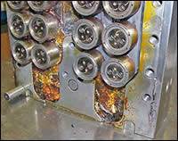
When the mold is in the press, the first noticeable sign of a flashed manifold is usually when smoke is seen rising from the top of the stationary side, or plastic oozes from places it shouldn’t. But there are more subtle clues that can point to a manifold leak, such as molds that produce periodic incomplete shots or occurrence of shorted-out heaters and thermocouples in a particular quadrant of the manifold. Paying attention to these signs can alert a processor to shut a mold down before the manifold is totally encapsulated.
It takes an experienced processor to notice these signs and request that the mold be pulled for a manifold inspection. Many will just let it go until the problem becomes obvious.
While pulling a mold that is only suspected of a manifold leak would seem like a waste of production time to many processors, the eight to 10 hours it might take to do this could save several days if you catch the leak in the initial stages of total encapsulation.
If there is even the slightest suspicion that a manifold has flashed, push a few pellets of a red resin or other contrasting colorant into the end of the injection nozzle (wear a protective glove). Then shoot the mold two to four times to help locate the source of the leak.
Five-step solution
Here is an overview of the five basic steps to repairing an encapsulated manifold:
1. Disassembly. Remove the valve pins and clamp plate, and disassemble the mold to gain visual access to the back of manifold. Pay attention to clues that can point to the leak source—bent, broken, or galled valve pins and the amount and type of residue around the pin.
Remove enough plastic to facilitate separating the manifold and electrical box from the plate, so that you can clean these components separately.
2. Cleaning: Ultrasonically clean the clamp plate, manifold plate channels, counter-bores, and valve pins. Clean by hand the nozzles, heater, thermocouple wires, and manifold.
3. Troubleshoot: Inspect seal areas for obvious cracks, plates for hobbing, and bolts for looseness.
4. Assemble: Reinstall manifold. Perform an electrical check before completing assembly of remaining components. If all is well, complete assembly.
5. Final Check: Perform an electrical check while ramping heaters up to processing temperature with water flowing through the cooling channels.
Here’s a closer look at some of these steps, starting with disassembly.
On valve-gate molds with valve stems accessible from the back of the clamp plate, it is possible to remove the valve stems cold with a small slap hammer, but you risk breaking off the head of the stems, so it is usually safer to warm up the nozzles and (if possible) the manifold to about 250 F so the pins can be removed with less force.
Make sure the valve stems are numbered (use a carbide cutter in a hand-held grinder), mark a “home” location somewhere on the head or stem, and place them in a wooden or plastic base drilled with marked holes to keep the stems upright and separated.
Remove the backing plate (usually the “A”-side clamp plate) to gain access to the back side of the manifold. Here you might see your first clue: Look for the path of the red or other colored resin. Manifold and nozzle seals that fail will allow the plastic to flow from that point outboard and follow the path of least resistance. The plastic will flow through wire channels in a laminar manner, so the resin around the initial point of failure will be more burned (degraded). This means the freshest looking flow front is usually farthest away from the source of the leak and has been “cooking” the shortest time.
Notice the direction of the “shot waves” of resin that ripple away from the leak source, paying particular attention to the condition of the plastic. Is it burned (closest to the point of leakage) or fresh (last place to fill)?
Before attacking the plastic with a hammer and chisel, look hard for the source of the leak (the red resin really helps) and try to confirm by examining the seal point in this area—look for a resin film between the tooling that would indicate separation. If an area looks suspicious, remove the plastic and check things out before continuing on.
A faulty seal between a nozzle and the manifold is easy to detect, since the plastic rod formed at the junction should be smooth with no plastic “washer” attached to it.
At this point you will either discover the source of the leak or you will find nothing and proceed on with more melting, chipping, and cleaning. Make good use of the heat gun (a Master Appliance Heat Gun #HG-751-B works great) and your brass chisel. The heat gun will soften much of the plastic in the channels so that you can more easily remove it from around the wiring while carefully working your way down the channels.
If you find nothing initially, keep removing enough plastic to separate the manifold/nozzle/electrical-box assembly from the manifold plate. This will allow the plate to be cleaned ultrasonically while the nozzles and manifold are inspected and cleaned by hand. Crank up the ultrasonic tank temperature to 200 F and tilt the plate forward in the tank so the resin weepage will liquefy and run out of the counter-bores and channels.
While the plates are cleaning in the ultrasonic tank, you can now remove the nozzles from the manifold one at a time and look for signs of seal separation and feel or watch for loose bolts. If gate-tip edges are critical, wrap the tips in masking tape to protect them from accidental dings.
After all nozzles are removed from the manifold, set them aside (still connected to the electrical box) and clean the manifold with a brass putty knife and then with a fine/medium-coarse Norton stone.
Next month we will begin the inspection and assembly phase.
Steven Johnson worked as a toolmaker for 26 years, rebuilding and repairing multicavity molds for Calmar Inc. and then as mold-maintenance engineer for Hospira Inc., a medical device manufacturer. Today, he is the maintenance systems manager for Progressive Components and has his own business, MoldTrax in Ashland, Ohio, which designs and sells software for managing mold maintenance (www.moldtrax.com). He can be reached at steve@moldtrax.com or (419) 289-0281.
Related Content
Processing Megatrends Drive New Product Developments at NPE2024
It’s all about sustainability and the circular economy, and it will be on display in Orlando across all the major processes. But there will be plenty to see in automation, AI and machine learning as well.
Read MoreAutomation in Thermoforming on the Rise
Equipment suppliers’ latest innovations exemplify this trend driven by factors such as labor shortages, higher-speed thermoformers and tighter quality control.
Read MoreAutomation Evolution: From Robots to Work Cells, Solo Devices to Integrated Systems
Injection molding automation has progressed from devices to systems, from simplicity to more complex capabilities. The author traces this development through various levels of automation – all still available choices today – and analyzes the costs and capabilities for each level.
Read MoreA Cost Saving Modular Approach to Resin Drying Automation
Whether implementing a moisture-sensing closed-loop system for a single dryer, or automating an entire plant, technology is available to take the guesswork and worry out of resin drying. Using a modular approach allows processors to start simple and build more capabilities over time.
Read MoreRead Next
How to Clean a Flashed Hot Manifold-Part One
As I rounded the corner of our shop, I was confronted by a large flock of white shirts gathered around a mold on my bench.
Read MoreHow Polymer Melts in Single-Screw Extruders
Understanding how polymer melts in a single-screw extruder could help you optimize your screw design to eliminate defect-causing solid polymer fragments.
Read MoreWhy (and What) You Need to Dry
Other than polyolefins, almost every other polymer exhibits some level of polarity and therefore can absorb a certain amount of moisture from the atmosphere. Here’s a look at some of these materials, and what needs to be done to dry them.
Read More



.png;maxWidth=300;quality=90)


