
How Polymer Melts in Single-Screw Extruders
Understanding how polymer melts in a single-screw extruder could help you optimize your screw design to eliminate defect-causing solid polymer fragments.


The melting (or devitrification) process can be a rate-limiting process for some single-screw extruders. For these situations, the extruder drive train, extrudate temperature and downstream equipment are not rate limiting. As the screw speed and rate are increased, a maximum rate will occur where the extrudate is completely molten and free of solid polymer fragments. At slightly higher screw speeds, solid polymer fragments start to appear in the extrudate, causing defects in the product.
If fresh resin and masterbatch resins or color concentrates are fed to the extruder, the defects will be solid polymer fragments from one of the resins. But since the fresh resin is added at the highest level, statistically the defects are likely to be from the fresh resin. If the drive train is not limiting, this defect can be eliminated via screw design.


Solid polymer fragments are likely to be discharged from the extruder at high screw speeds because of the processes governing solid conveying, melting, and the metering sections. For example, if the screw speed is doubled the pumping capacity of solids conveying and the metering sections will also double. The melting flux, however, will only increase by a factor of about 1.4 times. The melting flux has units of kg/(hr m2) where the unit area term is the area of the barrel wall where melting is occurring.
The melting capacity is defined as a melting flux times the barrel area available for melting.
The melting capacity is defined as a melting flux times the barrel area available for melting. As the screw speed is increased and because the melting flux does not increase at the same rate as solids conveying and metering, additional area at the barrel wall is needed for melting. Thus, the solid bed is forced downstream such that more area at the barrel wall will be used to melt the additional resin.
Because of limited barrel surface area, eventually some solids will not be melted and will instead discharge with the extrudate. A photograph of a black- tinted HDPE thin-wall pipe cross section is shown in Fig. 1. Here the large white areas do not contain pigment because they were discharged from the extruder as a solid fragment. The fragments exited the extruder because the rate was higher than the melting capacity of the machine. Short term, the only solution to mitigate these fragments is to decrease the extrusion rate.
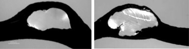
FIG 1 Solid-black fragments in thin-wall HDPE pipe. The feedstock was a natural-colored resin with a black masterbatch.
The Maddock Solidification Experiment
The melting process can be studied using a Maddock solidification experiment. For this experiment, a small amount of color masterbatch is added to fresh resin at a ratio of about 200 parts fresh resin to one-part masterbatch. The mix is added to the hopper.
When the discharge becomes fully tinted by the colorant, the rotation of the screw is stopped, and the barrel zones are placed on full cooling. The die and transfer line are removed, and the pellets in the hopper are removed using a vacuum cleaner. After the resin is solidified in the extruder, the screw is pushed out, as shown by Fig. 2 for an ABS terpolymer. Next, the solidified resin is removed from the screw and sectioned, as shown in Fig 3 and 4.
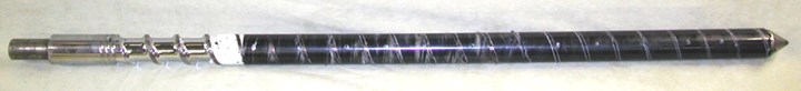
FIG 2 Screw with solidified ABS resin from a Maddock-solidification experiment.
A cross section early in the melting process is shown in Fig. 3. The white regions were compacted pellet solids at the moment that screw rotation was stopped. The black regions were molten resin. A thin melt film exists between the solid bed and the barrel wall. The rotation of the screw causes viscous dissipation of energy to occur in this film. Some of the energy conducts into the solid bed and melts additional resin.
The newly molten resin is carried away in the melt film and conveyed to the melt pool by the motion of the screw. About 80% of the melting occurs at the barrel side, and the remainder occurs at the other edges of the solid bed. This is why the melting process requires area at the barrel wall and why the melting process is presented as a melting flux with units of kg/(hr m2).
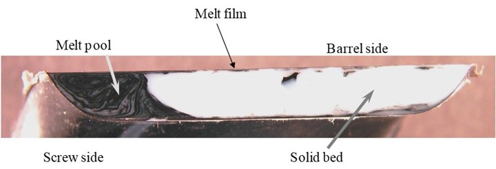
FIG 3 Cross section in the early portion of the screw’s melting section. White areas were solids at the time screw rotation was stopped. Black areas were molten resin.
The melting profile for a 21-diam long extruder is provided in Fig 4. Notice the solid bed becomes smaller, and the size of the melt pool becomes larger as melting progresses downstream. Eventually melting is completed. If the screw speed is increased, the solid bed will move downstream and into the metering channel as more surface area at the barrel wall is required for melting.
At diameter 18, the cross section shows that solids are not present, but at diameter 19 some solids are visible. This indicates that solid bed breakup has occurred. Solid bed breakup decreases the melting capacity of the extruder, and it is more likely to occur at higher screw speeds. Moreover, it typically leads to solid polymer fragments in the extrudate.
Solid bed breakup decreases the melting capacity of the extruder, and it is more likely to occur at higher screw speeds.
If the screw speed is high enough, then solid polymer fragments can be discharged with the extrudate. As an example, the same extruder was operated with the same blend of natural resin (with a small level of TiO2) and black colored masterbatch as a function of screw speed. The extrudate was passed through a 0.5-in. diam die to make logs. The cross sections of the logs are shown in Fig 5.
At screw speeds less than about 70 rpm, the extrudate is fairly well mixed and free of solid polymer fragments. At higher screw speeds, solid polymer fragments are apparent in the logs. Moreover, the level of solids increases with increasing screw speed. As before, the best short-term solution to the problem is to decrease the rate until the polymer fragments are not observed.
All screws will discharge solid polymer fragments if the screw speed is high enough. Some design styles, however, can operate at higher rates without discharging solids. These design types include screws with a combination of a barrier melting section followed by a Maddock mixer and several patented high-performance screws. These designs all work by forcing all of the molten resin through segments of the screw that have tight dispersive mixing clearances.
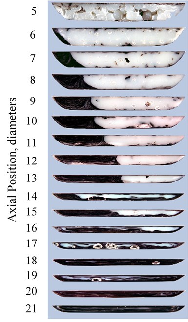
FIG 4 Melting profile for a 21-diam long extruder running a mixture of ABS and a small amount of black masterbatch.
For example, a Maddock mixer on a 3.5-in. diam screw would have a mixing flight undercut that is about 0.025 to 0.050 inch. As the material flows across the undercut, solid polymer fragments are trapped, melted, and dispersed into the molten resin, ng the extruder to operate at higher screw speeds and rates. Eventually, a screw speed will be reached where solid fragments are discharged from these screws too.
The melting process is the first opportunity for mixing, as shown in Fig. 3. For this experiment, the resin was 200 parts natural resin and only one part of a black masterbatch.
Here, primary mixing occurs during the melting process in the melt film. That is, as melting is taking place the newly molten resin is accelerated and stretched before ending up in the melt pool. This is evident by the relative uniformity of the black color in the melt pool. A downstream Maddock mixer or some other dispersive mixer would provide a secondary level of mixing and likely result in a homogenous extrudate.
For most processes, solid polymer fragments in the extrudate can be eliminated via screw design. Maddock mixers are excellent at trapping, melting, and dispersing solid polymer fragments. Moreover, a smaller undercut on the mixing flight provides an improvement in eliminating solids. For a 3.5-inch diam screw, the mixing flight undercut can be as small as 0.015 in, providing a gap between the mixing land and the barrel wall of 0.019 in (0.004 in flight clearance). This small gap will mitigate even small solid fragments.
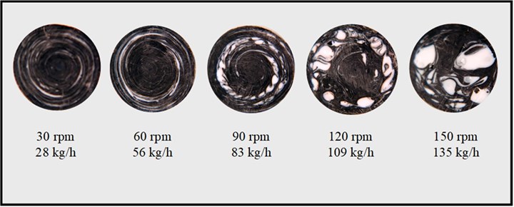
FIG 5 Cross-sectional views of extrudate samples at a letdown ratio of 100 to 1 of a natural ABS (with a small level of TiO2) resin with a black color concentrate. The large round white regions for the cross sections at screw speeds of 90 rpm and higher are solid polymer fragments discharged with the extrudate.
About the Author: Mark A. Spalding is a Fellow in Packaging & Specialty Plastics and Hydrocarbons R&D at Dow, Inc. in Midland, Mich. During his 37 years at Dow, he has focused on development, design, and troubleshooting of polymer processes, especially in single-screw extrusion. He co-authored Analyzing and Troubleshooting Single-Screw Extruders with Gregory Campbell. Contact: (989) 636-9849; maspalding@dow.com; dow.com.


Related Content

How to Select the Right Cooling Stack for Sheet
First, remember there is no universal cooling-roll stack. And be sure to take into account the specific heat of the polymer you are processing.
Read More
Why Are There No 'Universal' Screws for All Polymers?
There’s a simple answer: Because all plastics are not the same.
Read More
The Role Barrel Temperatures Play in Melting
You need to understand the basics of how plastic melts in an extruder to properly set your process and troubleshoot any issues. Hint: it’s not about the barrel temperature settings.
Read More
Part 2 Medical Tubing: Use Simulation to Troubleshoot, Optimize Processing & Dies
Simulation can determine whether a die has regions of low shear rate and shear stress on the metal surface where the polymer would ultimately degrade, and can help processors design dies better suited for their projects.
Read MoreRead Next

Mission (Nearly) Impossible: Estimating Extrusion Melt Temperature
Extrusion processors often ask screw designers to estimate the output and melt temperature of a new design in the works. Projected output of a new screw can usually be estimated fairly accurately. Melt-temperature estimate, however, is another story
Read More
Understanding Melting in Single-Screw Extruders
You can better visualize the melting process by “flipping” the observation point so the barrel appears to be turning clockwise around a stationary screw.
Read More
Looking to Run PCR on a Single Screw? Here’s What to Keep in Mind
Just drop it in and mix it up? Sorry, there’s a lot more to it than that. Here is some of what you need to consider.
Read More