
How to Configure Your Twin-Screw Extruder: Part 3
The melting mechanism in a twin-screw extruder is quite different from that of a single screw. Design of the melting section affects how the material is melted, as well as melt temperature and quality.


The melting mechanism in a co-rotating twin-screw extruder is unique. Single-screw processes rely on heat from the barrel and friction between the barrel wall and the polymer conveyed between the screw flights to melt the polymer. The melting mechanism in a twin-screw extruder is quite different. A twin-screw extruder works the polymer mechanically using kneading blocks to stretch, shear and fold the polymer to generate heat.
In the previous article (May 2023) we discussed feeding the polymer and other raw materials into the extruder and conveying the solid particles in the extruder to the melting section, which is the next unit of operation along the length of the extruder screw. In this article, we will discuss how the polymer is melted by the kneading blocks and how the design of the melting section affects how the material is melted and the melt temperature and quality.


Function of the Melting Section
All compounding operations take place in the molten state. While this is an obvious statement, configuring the screw to melt the polymer is not trivial. A melting section that is too severe will result in high melt temperatures, which may exceed the degradation temperature of the polymer, potentially causing degraded or burnt polymer.
Alternately, a melting zone that is too mild may not sufficiently melt the polymer. Polymer type, particle-size distribution and material melting point all contribute to the mechanics that take place during melting. A melting zone that is too mild could allow unmelted particles to pass through, resulting in an inhomogeneous product.
Figure 1 shows a picture of an assembled melting section. Solid material is conveyed from the feed throat (from the right in this picture). As the solids are pushed from the conveying elements onto the kneading blocks, the shearing action of the discs stretches and pulls the material. The solid particles of the feed are mixed while the work imparted to the polymer causes the temperature of the material itself to rise. The increase in temperature, in turn, causes the polymer to soften and then melt.
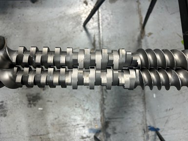
FIG 1 Melting section in Leistritz 40-mm MAXX Extruder. (Photo: Polymers Center)
Kneading Blocks
A kneading block consists of a series of discs or paddles in which each disc is offset by a given angle from the previous disc. This stagger angle and the width of each disc determines the severity of the work that is imparted by the kneading block. The direction of the stagger also determines whether the kneading block conveys the material downstream (forward conveying) or upstream (backwards conveying).
Kneading blocks are used not only for melting but also for mixing. The mixing and melting actions occur simultaneously in the melt zone of the extruder. In this article, we will discuss the melting mechanism. We will focus on mixing in a future article.
Figure 2 shows a forward-conveying kneading block. Looking at the end of the kneading block, each disc on this element is offset by 60° from the disc immediately preceding it. It should be noted also that the general motion from one disc to the next is clockwise. This is the same rotational direction as the conveying screws.
As this kneading block turns in the screw, its rotation will push the polymer forward — i.e., a forward-conveying kneading block.
Kneading blocks are used not only for melting but also for mixing.
The stagger angle affects the amount of energy that is imparted to the polymer in part by how much it conveys the material forward. Considering a conveying element, the rotation of the screw pushes the polymer forward. Likewise, a forward-conveying kneading block also pushes most of the polymer forward. Some polymer passes over the tip of the disc and is sheared against the barrel wall, some is transferred to the adjacent kneading block of the other screw, and a small amount leaks back upstream in the barrel. The combination of these three actions cause the polymer temperature to rise and conveys the polymer forward.
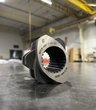
FIG 2 A 60° forward-conveying kneading block. (Photo: ENTEK)
One method used by some manufacturers to specify kneading blocks can be seen etched on the side of the kneading blocks in Figs 2–4. The shorthand coding for a kneading block uses the following coding:
KB#-2-##-XX, where
KB6 — Signifies a kneading block with six discs.
2 — Designates that the element is a bi-lobe element. The shape of the discs is such that they form an oval. This is similar to conveying elements in which a bi-lobe element has two separate flights starting 180° from each other.
## — The first number is the length of the element in mm. The kneading blocks shown are all 60-mm long.
XX — The second number is the stagger angle. In Fig. 2, the angle is 60°. In Fig. 3 the angle is 90°.
Other suppliers designate their kneading blocks as:
KB ##/X/%%, where
KB — Designates a kneading block
## — Specifies the angle between discs
X — Indicates the number of discs
%% — Is the length of the element in mm.
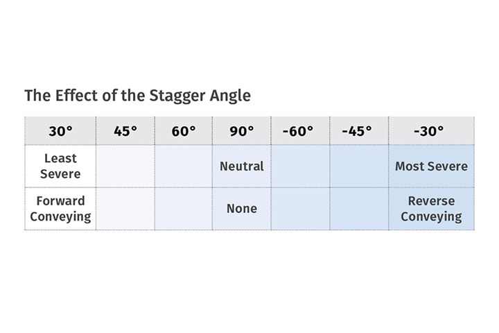
A kneading block with 30° between discs has minimal mixing and conveys the material forward the best. A 45° kneading block imparts a little more energy to the polymer with increased mixing but slightly less forward conveying. A 60° kneading block has poor forward-conveying capability but is much more efficient at mixing and imparts more energy to the material.
As the stagger angle increases, the forward pumping ability of the kneading block decreases until the angle reaches 90°. At 90° the kneading block is neutral, polymer is mixed but does not move forward due to the rotation of the kneading blocks. Figure 3 shows a neutral kneading block with the discs arranged at 90° from each other.
As the conveying capability decreases, more polymer passes over the end of each disc resulting in more energy being imparted to the polymer and increased mixing.
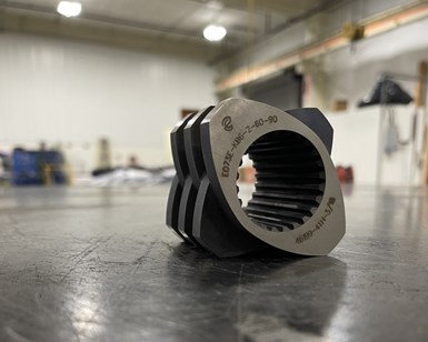
FIG 3 A 90° neutral kneading block. (Photo: ENTEK)
Disc Width
Another factor that greatly affects melting in a twin-screw extruder is the width of the disc. A kneading block may consist of as few as three discs and as many as seven, although typically, they have either four or five discs per kneading block. Often the number of discs is constant and the length of the kneading block is adjusted to increase or decrease the width of the discs.
The wider the discs, the more energy that is imparted to the polymer. As the kneading block rotates in the extruder, the polymer can only flow in one of two directions: over the tip of each disc or around one disc to the next disc.
Configuring the screw to melt the polymer is not trivial.
Increasing the width of the disc causes more polymer to flow over the tip of the disc. A narrow disc kneading block will essentially slice through the polymer while a wide disc will act more as a plow.
The space between the tip of the disc and the barrel wall is where the shear rate is the greatest. Polymer passing through this area is subjected to the highest shear forces in the extruder. A wide disc kneading block will impart more energy to the polymer than a narrow disc kneading block. This increased energy input will result in higher melt temperatures.
Reverse-Conveying Kneading Blocks
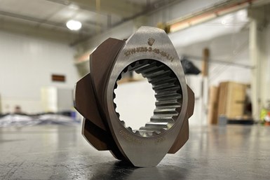
FIG 4 Reverse-conveying kneading block. (Photo: ENTEK)
The final type of kneading block that is used in the melting section is the reverse-conveying kneading block. This type of kneading block is the most severe as it pumps the molten polymer back upstream. In this case, the smaller the stagger angle, the more severe is the work on the polymer.
Figure 4 shows a reverse-kneading block. For many manufacturers, forward-conveying elements curve towards the right. The rotational direction from one disc of a kneading block to the next is clockwise. As such, a reverse-conveying element has flights or discs that rotate counterclockwise. These manufacturers designate the reverse-conveying elements using the same nomenclature as for the forward-conveying elements followed by “LH.” The LH stands for Left-Handed, as these are left-handed elements and forward -conveying elements are right-handed.
Other manufacturers designate the reverse-conveying elements with the letters “RE,” which stand for Reverse Element. The reason for this is that these screw elements rotate in the opposite direction to neighboring elements.
The effect of the stagger angle can be seen in the accompanying table:
Assembling the Melting Section
The design of the melting section depends on the type of material being processed. Factors such as whether a polymer is crystalline or amorphous, has a high or low melt viscosity, or is being processed near its decomposition temperature must be considered when designing the melting section of the screw configuration.
The condition of the feed is also critical. Is only one polymer or a mixture of several polymers being fed through the feed throat? What types of fillers and additives are being fed with the polymers? Do one or more additives melt at a significantly lower temperature than the polymer? These factors can affect which types of kneading blocks are best suited. Is a melting zone consisting of a continuous section of kneading blocks appropriate or is a configuration of alternating kneading blocks and conveying elements a better design for the material being compounded?
One thing that I will repeat often is that while we can discuss the science behind the action of the screw elements, screw design is an art. Engineers will design screws differently to achieve the same function. This does not necessarily mean that one design is wrong while another is right. They may just be different, but both are acceptable if the quality of the product meets the requirements.
Screw design is an art. Engineers will design screws differently to achieve the same function.
Figure 1 shows a melting section for a 40-mm twin-screw extruder. The kneading blocks for this extruder consist of four discs each. Solid material is fed from the right side of the photo by the conveying elements. The first element in the melt zone is a 30° kneading block followed by three 60° kneading blocks. Three 90° neutral kneading blocks complete the melting section.
As the feed material enters the melt zone, it is transferred from conveying elements to a 30° kneading block. This helps to pull the feed into the melting zone and transition from conveying elements to kneading blocks with minimal backflow of the polymer. The 60° kneading blocks then provide stronger work input to begin the melting process while still conveying the material forward. Most likely the polymer begins to melt between the end of the 30° kneading block and the middle of the first 60° kneading block.
The 90° kneading blocks serve two functions. The first is to impart an even higher amount of energy to the polymer to melt the polymer and to raise the melt temperature to the recommended temperature for processing. The second function that the 90° kneading blocks perform is to act as a restriction preventing the material from passing through the melt zone too quickly. This ensures that the local residence time of the polymer in the melt zone is sufficient to ensure that all of the polymer that passes through the melt zone is molten. The restriction created by the 90° kneading blocks will act as a melt dam increasing the fill of molten polymer in this region of the screw.
Some alternative designs include the following:
• Reverse kneading blocks: A left-handed kneading block can be used to increase the amount of restriction at the end of the melting section. Pumping material upstream can improve melting, particularly of crystalline polymers and high-temperature polymers, by increasing the time that the polymer is worked by the kneading blocks.
• Reverse conveying element: A left-handed conveying element is even more severe than a left-handed kneading block. This provides even more backflow for greater mixing, increased homogeneity of the melt and imparting higher melt temperatures. Some formulations even require use of a left-handed kneading block followed by a left-handed conveying element.
• Separating the kneading blocks with conveying elements: For some polymers, a single long series of kneading blocks is not the best configuration. Some issues that may result range from too high a melt temperature to surging in the extruder due to uneven flow or uneven melting. One approach is to design several short melting sections separated by a conveying element. This may be configured as, for example, two 45° kneading blocks followed by a 90° kneading block, which is repeated once or twice, followed by a reverse 45° or 60° kneading block to ensure complete melting.
Now that the polymer is molten, we will discuss next time how other materials such as liquids, low-melting-point additives, and fibers can be added into the melt.
ABOUT THE AUTHOR: Kenneth W. Russell has more than 35 years’ experience working with polymer processing and resin companies. He has expertise in polyolefin polymerization, polymer compounding, reactive extrusion, and film and sheet extrusion. In 2014 he started Optimized Compounds LLC, providing consulting services in reactive extrusion, polymer compounding, product development, process optimization and scale-up with clients worldwide. In 2021, he joined GEM Plastics, a manufacturer of HDPE sheet, providing process engineering, operator and technician training, and materials expertise. Contact: kwrcompounding@gmail.com.


Related Content

Green’s the Theme in Extrusion/Compounding
The drive toward circular economy is requiring processors to make more use of PCR. Machine builders at K—across all extrusion processes—will be highlighting innovations to help them do just that.
Read More
How to Configure Your Twin-Screw Extruder -- Part 2
Follow these tips to configure your twin-screw elements to promote feeding and solids conveying.
Read More
Sustainability Among the Many Niches at Niche Polymer
Founded in 1987, Niche Polymer continues to grow—both organically and through acquisition—by focusing its product-development efforts on ever-changing market needs. Adding value to both industrial and post-consumer scrap is a growing part of this effort.
Read More
How to Maintain Pelletizing Quality When Acid Attacks
Developments in the chemistry of polymers and additives have made corrosion a real problem in pelletizers. Here’s how to ward it off.
Read MoreRead Next

How to Configure Your Twin-Screw Extruder -- Part 2
Follow these tips to configure your twin-screw elements to promote feeding and solids conveying.
Read More
How to Configure Your Twin-Screw Barrel Layout
In twin-screw compounding, most engineers recognize the benefits of being able to configure screw elements. Here’s what you need to know about sequencing barrel sections.
Read More
Why (and What) You Need to Dry
Other than polyolefins, almost every other polymer exhibits some level of polarity and therefore can absorb a certain amount of moisture from the atmosphere. Here’s a look at some of these materials, and what needs to be done to dry them.
Read More