
How to Configure Your Twin-Screw Extruder -- Part 2
Follow these tips to configure your twin-screw elements to promote feeding and solids conveying.


The configurability of the twin-screw extruder offers a unique level of flexibility. Last time we discussed the functionality of the barrel sections and how barrel sections can be moved to optimize the process.
In a twin-screw extruder, screw design is a combination of art and science. The screws consist of a series of individual segments that are positioned on a shaft. These segments, or elements and can be configured according to the unit operations that are required along the length of the extruder. Each screw element has a specific function. Minor changes in element design and placement can affect how materials are mixed, melted or conveyed.


We will begin our discussion of the screw configuration of a fully intermeshing co-rotating twin-screw extruder with the feed section.
Function of the Feed Section
The function of the feed section, obviously, is to accept the material being fed to the feed throat of the extruder and to convey the solids to the melting section of the extruder. Solids conveying is the unit operation occurring in this region of the extruder. Most plastics processes that utilize a single screw are flood-fed: the extruder hopper is filled with the polymer or a mixture of polymer and additives. The rotation of the screw pulls the material into the extruder or molding machine.
A twin-screw extruder, on the other hand, is starve-fed. Feeders meter the materials into the feed throat at a steady, controlled rate. The processing rate of a twin-screw extruder is controlled by the feeders and is independent of the rotational speed of the screws. The amount of material fed to the twin screws must be controlled to prevent the screws from locking up, which will occur if the feed throat becomes flooded with material.
(FIG 1) Top view of conveying elements for a twin-screw, co-rotating, intermeshing compounding extruder. Note that the end is oval, and each flight starts at a position 180° from the other flight. (Photo: CPM Century Extruders)
The barrel section to which material is being fed is the feed throat. This can be the first or second barrel section. The feed can be free-flowing pellets, a cohesive mixture like a paste, or a light bulky powder. The screw must be designed with long open flights to allow the feed to drop into the root of the screw to be carried into the extruder.
Once the material is fed to the extruder, the screws then convey the solids into the extruder and along the length of the extruder to melting section, where the polymer is melted. We will discuss the melting section specifically in the next installment.
The length of the feed section can vary depending on the overall compounding requirements. When designing a screw, consider the overall compounding function that is to take place in the extruder. Is the goal to simply pelletize the polymer from powder? Is this a glass- or mineral filled compound or a heavily loaded masterbatch of pigments and additives? The length of the feed section should be designed so as to delay the melting of the polymer until necessary for the melting, mixing and venting required.
Polymers develop a heat history every time they are melted. This heat history is a function of the number of times the polymer is melted, how long the polymer remains molten and the temperature of the melt in its molten state. This heat history has a direct effect on the polymer properties.
In compounding, actions to minimize the heat history of a polymer should be considered in the design and operation of the extruder. To that end, the length of the feed section is determined after taking into account the other unit operations that are required to compound the product. The feed section can be short or long as necessary so that the polymer is melted when required, but no sooner.
Make-up of the Screws
Each screw in a twin-screw extruder is configured by sliding elements, also known as screw bushings, along a shaft equal in length to the length of the extruder barrel. The two screws have to be perfectly matched for the screws to turn freely.
Each section of the extruder uses the elements that perform the function that is required in that section. The function of the feed section is to convey solids into the extruder without the materials softening or melting. The feed materials will remain a free-flowing solid as they are conveyed in the feed section.
Figure 1 shows a standard, bi-lobe conveying element. Screw elements can have one, two or three separate flights around the cylindrical core, although the most common design is the bi-lobe design with two flights. As you can see in Fig. 1, the end has an oval shape, and each flight starts at a position 180° from the other flight.
Conveying Elements
The two primary measurements that define a conveying element are the length of the element and the axial length for the flight to complete a full revolution around the element. The longer the length of the flight, the wider the channel for the solids to be conveyed. Likewise, as the length of the flight increases, the further the material moves in a single revolution.
A conveying element with a short flight length, also known as a “tight flight,” conveys material only a short distance, while a “wide flight” element will convey material much farther along the length of the extruder.
One system that some manufacturers use to identify their conveying elements is with a pair of numbers that represent the flight length divided by the length of the element.
Examples of this type of labeling include:
- 25/25: A conveying element that is 25-mm long with a flight that makes a full revolution around the element while advancing 25 mm in the axial direction.
- 40/40: This element is similar to the 25/25 except the element itself is longer (40 mm) and the flight takes 40 mm to complete a full revolution. The 40/40 element has a much wider flight than the 25/25 and therefore conveys the material farther down the extruder.
- 24/12: In this case, the flight would take 24 mm to complete a full revolution, but the element is only 12 mm long. This kind of element allows the engineer to maintain the 24-mm flight while only using 12 mm of space on the shaft.
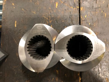
Figure 2 shows a special element used in the feed throat of the extruder, known as an SK element, or feed element. The side of the flight that pushes the material has been cut away, forming a flatter surface that pushes the feed material more in an axial direction, compared with the standard conveying element, which has a curved surface. These elements would be designated as, for example, 90/90 SK.
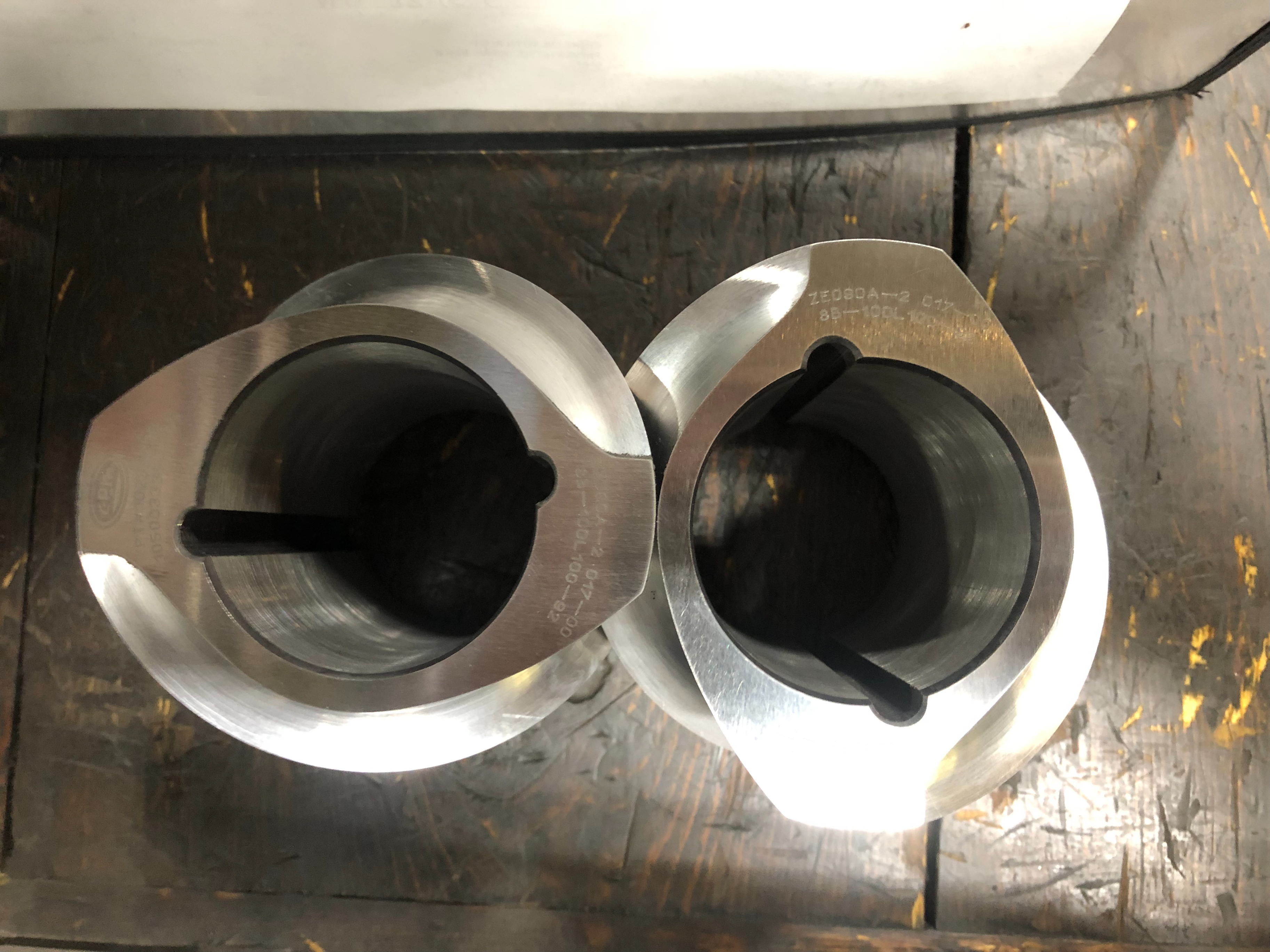
FIG 2 SK or feed elements are used in the feed throat of the compounding extruder. (Photo: CPM Century Extruders)
Another common terminology specifies the element with the following layout:
- Type of element:
- a. COC or GFA designates conveying elements.
- b. COF signifies the feed elements, similar to the SK used by others.
- The number of flights (or lobes). A “2” designates that these are bi-lobe elements.
- The flight length.
- The length of element.
An example of this can be seen in Fig. 3. This figure shows a standard feed-throat design with feed elements and conveying elements designated as, for example, COF-2-60-90 for a bi-lobe feed element that is 90-mm long with flights that travel 60 mm/revolution.
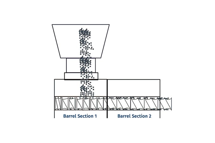
FIG 3 When designing the screw in the feed zone, the intent is to collect the material as it drops into the feed throat and quickly convey it into the extruder. A typical feed section is shown. (Illustration: K. Russell)
Configuring the Feed Throat
When designing the screw in the feed zone, the intent is to collect the material as it drops into the feed throat and quickly convey it into the extruder. As shown in Fig. 3, the SK elements (feed elements) are positioned directly under the feed throat. The number of elements is based on the length of the elements. Some manufactures will primarily produce elements that equal the length of one revolution of the flights. Others may manufacture longer elements. The feed elements are followed by standard conveying elements typically with the same flight length as the feed elements so that the feed is smoothly conveyed into the extruder.
Often a transition element is used that streamlines the pushing flight from the cutaway to the smooth, curved profile of the standard conveying element. This eliminates any sharp edges that can break off or in which material can build up.
The remainder of the feed section consists of wide-flight conveying elements up to the start of the melting section.
A tight-flight element is placed at in the first position on the shaft, upstream of the feed elements, to act as a mechanical barrier of sorts to keep powders and small granules from leaking though the stuffing box, which will cause excessive wear of the packing.
Designing the Feed Throat for Powders
Powders present a challenge for feeding, especially powders with a low bulk density and very small particle size. As the light powders fall through the feed hopper, air is carried down by the powder. The mixture of powder and air takes up a lot of volume, effectively choking the feed throat, which will reduce or stop the polymer feed.
Additionally, the entrained air then must escape from the extruder. The escaping air only has one pathway out of the extruder which is up into the feed hopper. This escaping air will flow up into the feed hopper and can cause a very light powder to fluidize. The suspended powder then accumulates until it drops in to the feed throat and the process repeats. Between the blockage in the feed throat and the disruption of the powder feed, entrained air can result in low feed rates and surging, among other issues.
Minimizing air entrainment and removing the air from the powder is critical to maintaining an economical feed rate. Some extruder manufacturers have developed special screw elements and barrel technologies to mitigate the issues with low-bulk-density powders and air entrainment. As these technologies are specific to each manufacturer, they are outside of the scope of this discussion.
In our last article, we discussed configuring the barrel so that the feed throat is located in Barrel Section 2. An atmospheric vent is positioned in barrel section 1 to provide a pathway for the air to escape without interfering with the falling powder. The air is still carried into the feed throat but now can travel upstream into the vent, where there is a clear pathway for the air to escape. This allows the powder to feed more easily and can improve the feed rate.
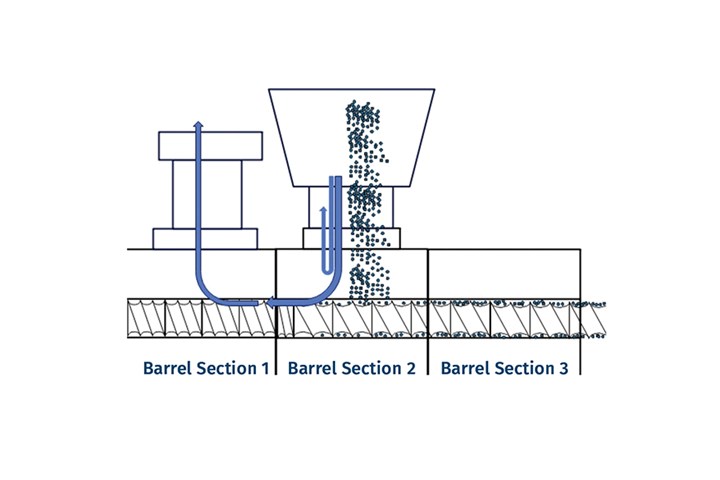
FIG 4 Feeding powders in Barrel Section 2 with Barrel Section 1 acting as a back vent is shown in Fig. 4. The air flow is depicted by the blue arrows. (Illustration: K. Russell)
Feeding powders in Barrel Section 2 with Barrel Section 1 acting as a back vent is shown in Fig. 4. The air flow is depicted by the blue arrows. As in the standard feed-throat configuration, SK conveying elements are located directly in the feed throat, followed by standard conveying elements. Both the SK feed elements and the conveying elements in this section should be the elements with the largest flight lengths that are available for the given extruder diameter to provide the maximum channel width to carry the powder.
Upstream of the feed throat, tight conveying elements are used to continuously push any powder forward, again acting like a mechanical seal. The tighter the flights, the more forward motion is available to prevent backup of the powder. The air, though, can pass through this barrel and out the vent, as these elements should not have much material in them, if any.
As we continue along the length of the extruder, we will discuss the screw configuration in the melting section of the twin-screw in our next column.
ABOUT THE AUTHOR: Kenneth W. Russell has more than 35 years’ experience working with polymer processing and resin companies. He has expertise in polyolefin polymerization, polymer compounding, reactive extrusion, and film and sheet extrusion. In 2014 he started Optimized Compounds LLC, providing consulting services in reactive extrusion, polymer compounding, product development, process optimization and scale-up with clients worldwide. In 2021, he joined GEM Plastics, a manufacturer of HDPE sheet, providing process engineering, operator and technician training, and materials expertise. Contact: kwrcompounding@gmail.com.


Related Content

How to Stop Flash
Flashing of a part can occur for several reasons—from variations in the process or material to tooling trouble.
Read More
Why (and What) You Need to Dry
Other than polyolefins, almost every other polymer exhibits some level of polarity and therefore can absorb a certain amount of moisture from the atmosphere. Here’s a look at some of these materials, and what needs to be done to dry them.
Read More
Are Your Sprue or Parts Sticking? Here Are Some Solutions
When a sprue or part sticks, the result of trying to unstick it is often more scratches or undercuts, making the problem worse and the fix more costly. Here’s how to set up a proper procedure for this sticky wicket.
Read More
How to Get Rid of Bubbles in Injection Molding
First find out if they are the result of trapped gas or a vacuum void. Then follow these steps to get rid of them.
Read MoreRead Next

How to Configure Your Twin-Screw Barrel Layout
In twin-screw compounding, most engineers recognize the benefits of being able to configure screw elements. Here’s what you need to know about sequencing barrel sections.
Read More
People 4.0 – How to Get Buy-In from Your Staff for Industry 4.0 Systems
Implementing a production monitoring system as the foundation of a ‘smart factory’ is about integrating people with new technology as much as it is about integrating machines and computers. Here are tips from a company that has gone through the process.
Read More
Lead the Conversation, Change the Conversation
Coverage of single-use plastics can be both misleading and demoralizing. Here are 10 tips for changing the perception of the plastics industry at your company and in your community.
Read More